The Duesenberg Multibender enables you to play authen-
tic sounding pedalsteel licks on nearly every normal electric
guitar or lapsteel with a flat top. You can raise or lower Indi-
vidual strings from 1 to 3 half tones (depending on the string
gauge used) by pressing with the palm of the right hand on
one or more of the multibender‘s levers, which is normally
done with a foot pedal or knee lever on a pedalsteel guitar.
The levers are attached to an axle behind the center sup-
port. The strings to be bent are fixed to the levers and then
run over rollers through the center support. Each lever has
two screws for adjusting the resting point and the amount
of pitch change.
MANUAL
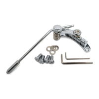
If you wish to add or remove a lever, now would be the
best time to do this. Loosen the two Allen screws on the
end of the base plate and slide the axle to one side. When
adding an extra lever, don‘t forget to install the enclosed
washer which prevents friction between the levers. When
completed, slide the axle back in place and tighten the two
Allen screws.
Mounting preparation
First of all make sure that the height of the multibender‘s
bridge saddles (11-14 mm) is compatible to the given neck
angle on the guitar so that the action of the guitar can be
properly adjusted.
Please note: The metal ear on the right side of the multi-
bender‘s base plate is meant to be used on a guitar with a
tremolo routing and must otherwise be removed to avoid
damage to the surface of the instrument!
Installation on a body without tremolo routing
Before removing the original bridge, first measure the
distance between the nut and the bridge saddle of the high
e-string. This measurement is needed for the exact positio-
ning of the Multibender bridge.
Before positioning the Multibender it is recommended to
protect the respective area on the guitar top using masking
tape to avoid scratching the surface.
Place the Multibender on the guitar top so that the high
e-string saddle position matches the previous measure-
ment (see above). The front of the base plate should be per-
pendicular to the center line of the guitar. Then use a piece
of thread stretched between the nut and the bridge saddles
of the outer strings to center the bridge. When the distance
between the thread and the edge of the fingerboard is the
same on both sides, the bridge is in place.
Now mark the positions for the eight attachment screws
and drill the holes with a 2mm drill. Use the enclosed
screws to mount the bridge.
The basic equipment includes two levers. Theoretically
there is space for up to three additional levers, although
a maximum of three levers in total is recommended for
convenient operation.
Allen screws for securing the axle
Installation on a body with vintage tremolo routing
(i.e. Fender Stratocaster)
In this instance only the front six screw holes are needed.
A new positioning of the bridge is not necessary, because
the six original holes are in the right place. However, these
holes must be doweled and re-drilled with a 2mm bit.
If the guitar is equipped with a modern tremolo with a two-
bolt mounting system, the existing holes can not be used
for positioning the Multibender bridge. In this case follow
the instructions for installation on a body without tremolo
routing. It may be necessary to dowel the original holes.
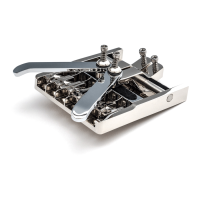
Front attachment holes (6 screws)
Metal ear
Front adjustment
screws
Rear adjustment screws
Lever axle
Rear attachment holes
(2 screws)
Center support
THREE STEPS AHEAD
DUESENBERG.DE
M
ULTIBENDE
R