COMPONENTS
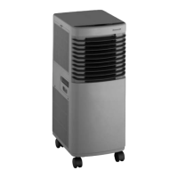
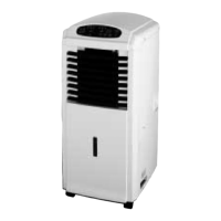
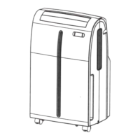
1. Control Panel
2. Air Outlet
3. Handle Hole
4. Caster
5. Cover
6. Air Filter
7. Water Outlet Drain
8. Air Outlet (Heat Exchange)
9. Water Outlet Drain
10. Power Supply Cord with Plug
11. Air Intake (Condenser)
12. Exhaust Nozzle
13. Exhaust Nozzle Connector
14. Exhaust Hose
15. Exhaust Duct Connector
WARNINGS
1. All wiring must comply with local and national
electrical codes and be installed by a qualified
electrician. If you have any questions regarding the
following instructions, contact a qualified electrician.
2. Check available power supply and resolve any
wiring problems before installation and operation of
this unit.
3. For your safety and protection, this unit is grounded
through the power cord plug when plugged into a
matching wall outlet. If you are not sure whether the
wall outlets in your home are properly grounded,
please consult a electrician. Do not use plug adapters
or extension cords with this unit.
INSTALLATION INSTRUCTIONS
Connect exhaust hose assembly to
the back of the unit. Extend hose to desired length and
locate the exhaust nozzle through the window for
ventilation (Fig. 1).
Exhaust Duct Set Assembly and Installation
1. Insert ends of exhaust hose (14) into exhaust nozzle
connector (13) by twisting counter-clockwise until it
stops.
2. Attach one exhaust nozzle connector (13) onto the
rear outlet of the unit. This is achieved by sliding the
exhaust nozzle connector of hose downward over the
exhaust outlet of unit (8) ensuring that the lugs on the
exhaust nozzle connector are engaged with the
grooves on the connector of unit (Fig. 2).
3. Attach the exhaust nozzle (12) to
the exhaust nozzle connector (13).
4. Extend the exhaust hose (14) and close the window
as far as possible trapping the exhaust nozzle (12)
(Figs. 3 and 4).
INSTALLATION INSTRUCTIONS
Air Conditioning with Installation
If required your appliance can also be installed semi-
permanently (Fig. 5).
Proceed as follows:
1. Drill a hole in an outside wall, through a door or a
window pane. The hole should be no larger than
125mm, and between 35cm and 100cm from floor
level. If you drill through a wall, we recommend
that you insulate that section with suitable materials.
(Figs. 6-7)
2. Fit the flange accessory fixture provided into the
hole.
3. Fit the exhaust hose in the housing at the back of
the appliance (Fig. 2).
4. Insert the other end of the exhaust hose to the
flange already placed in the hole (Fig. 7).
NOTE: When installing the air conditioner semi-
permanently, you should leave a door slightly open
(as little as 1cm) to guarantee sufficient
ventilation.
OPERATING INSTRUCTIONS: CONTROL PANEL
Emergency ON/OFF Switch
This switch is used when unit needs temporary on/off.
When pressed, unit starts running. The running mode
and fan speed mode are set at auto. When you press
the emergency button again, unit stops running.
Water Full Indicator
1. When lit, the condensation water inside unit can’t be
discharged and the condensation water level has
reached full.
2. When unlit, condensation water discharges out of
6
ENGLISH


 To Next Page