17 Appendix II: Modbus
D−LX 200, D−LX 720 153
17 Appendix II: Modbus
17.1 General information
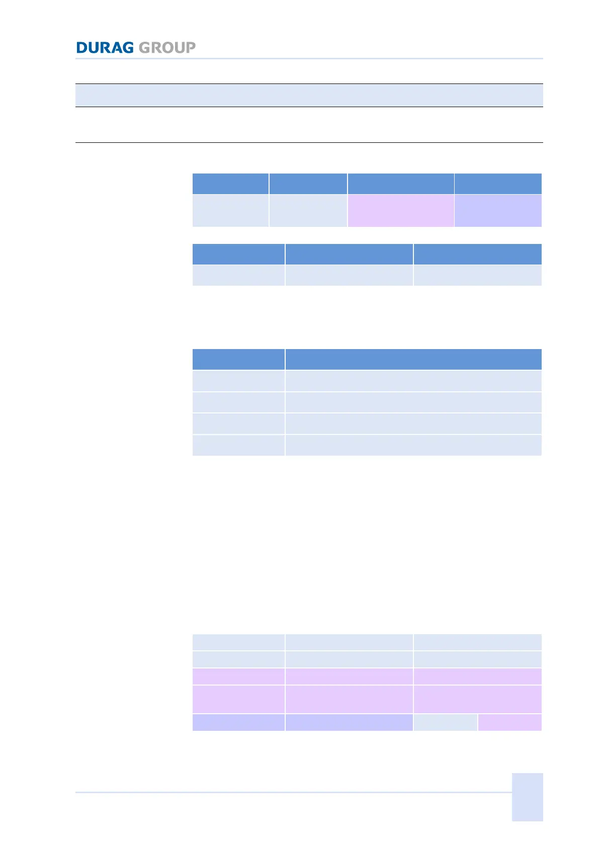
Table 17.1: Modbus RTU Message Frame
Slave individual addresses
Table 17.2: Modbus-Slave Address Range
The D−LX 200, D−LX 720 flame monitor supports the following Modbus
Function Codes:
Function Code description
Read holding register (16Bit)
Read input register (16Bit)
Write Single Register (16Bit)
Write Multiple Register (16Bit)
Table 17.3: Modbus Function Code
If an invalid Modbus enquiry is sent to the D−LX 200, D−LX 720 this sends an
appropriate Exception Message as the response; e.g. if the Function Code is
not supported or if the enquiry is for an invalid data address.
If a Function Code is not supported, the Modbus exception 01 "ILLEGAL
FUNCTION" is returned.
If an attempt is made to read from or write to a non-existent or blocked
memory area, the Modbus exception 02 "ILLEGAL DATA ADDRESS" is sent.
Modbus FunctionCode(0x03..0x04) Read 16Bit Registers
(for details see Modbus-Specification)
Request
Quantity of Input
Registers
Table 17.4: Modbus FunctionCode(0x03..0x04) Read 16BitRegisters Request
 Loading...