18
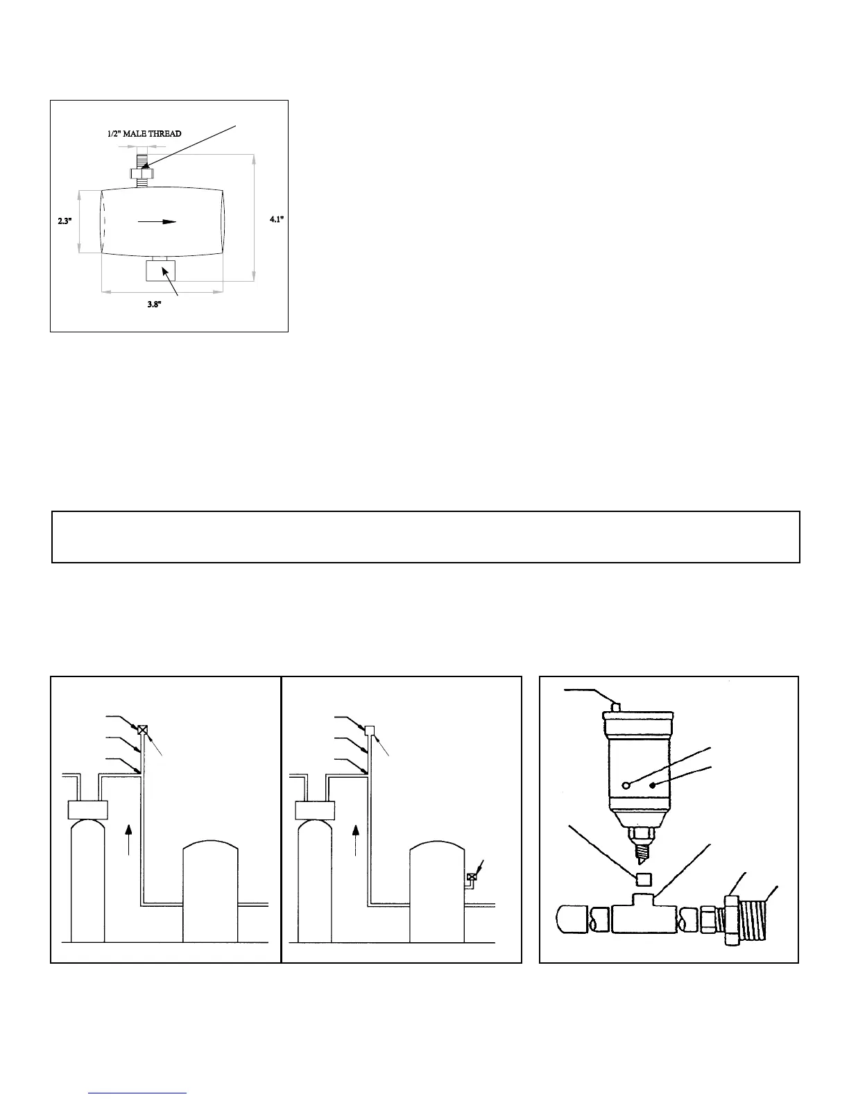
1.AirReleaseCapmustbelooseorremovedtoallowairtoescapefromvent.
2.VentBushing1/2”x1/8”
3.Toopeningonsideofretentiontank(approximately1/2wayup,frombottomoftank)
4.3/4”x3/4”x1/2”coppertee
5.3/4”adapterwithbushingtotank
NOTE: The Braukman air vent is not approved for use in the State of Wisconsin. An approved air to water tank and/or air
vent should be used with this application in the State of Wisconsin.
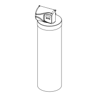
The Braukman Air Vent must be installed at the highest point of the plumbing, between the pressure tank and filter (see
Fig. 7). Please note that the Braukman Air Vent (A) is mounted on a four to six inch pipe extension (B) at the elbow (C) of
the highest point. This enables the vent to better collect any excess air created by the hydrocharger.
To use the Braukman Air Vent on an air-to-water pressure tank, install it approximately halfway up the side of the tank, as
shown in the detailed drawing below.
open
closed
1
2
4
3
Figure7A Figure7B
A
Braukman
Air Vent
Braukman
Air Vent
Pressure
Tank
(Diaphragm)
Pressure
Tank
(Air to
Water)
See
Figure 8
B
C
A
B
C
Out InOut In
5
Figure8
Braukman Air Vent Installation
Set hydrocharger by following these steps:
A. Open nearest faucet until pump starts, then close faucet.
B. Place a finger over suction port (Fig. 6) A slight suction should be detected
for a minimum of 20 seconds or for approximately one-third of pumping cycle
whichever is greater.
C. If suction duration is too short, increase by turning water flow adjusting screw
(Fig. 6) clockwise. To decrease duration, turn counterclockwise.
D. Repeat Steps A through C until proper setting is obtained. When the duration
of the suction is too long, cold water may have a “milky” appearance caused
by excess air in system. Correct this condition by reducing the duration of suc-
tion. This condition is one commonly associated with bladder-type pressure
tanks. In extreme cases excess air prevents the system from performing satis-
factorily, consequently it is essential to install an air relief valve (such as a
Braukman) in the proper location.
17
Figure 6
Air Suction Port
Screw to adjust
flow rate