14
13
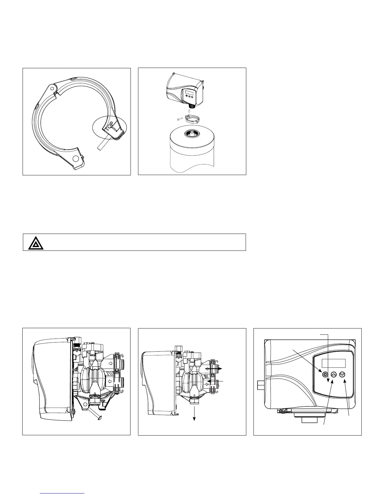
2. Familiarize yourself with the location
of the inlet, outlet and drain on the
control valve. Be very careful not to
get the controls wet.
3. Familiarize yourself with the buttons
on the timer control.
Drain 1/2”
Inlet
Outlet
2
Timer Controls
DOWN
button
UP button
Extra Cycle
Button
3
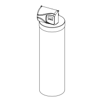
1. Clamp Ring – The clamp ring con-
nects the control valve to the tank
and provide an easy way to discon-
nect tank during control valve servic-
ing. Make sure that the clamp ring
screw is tightened.
The “Clamp Ring” should secure the valve with the top of the flange
facing up. Please note “top” on the clamp ring.
1
Installation Steps: