15
14
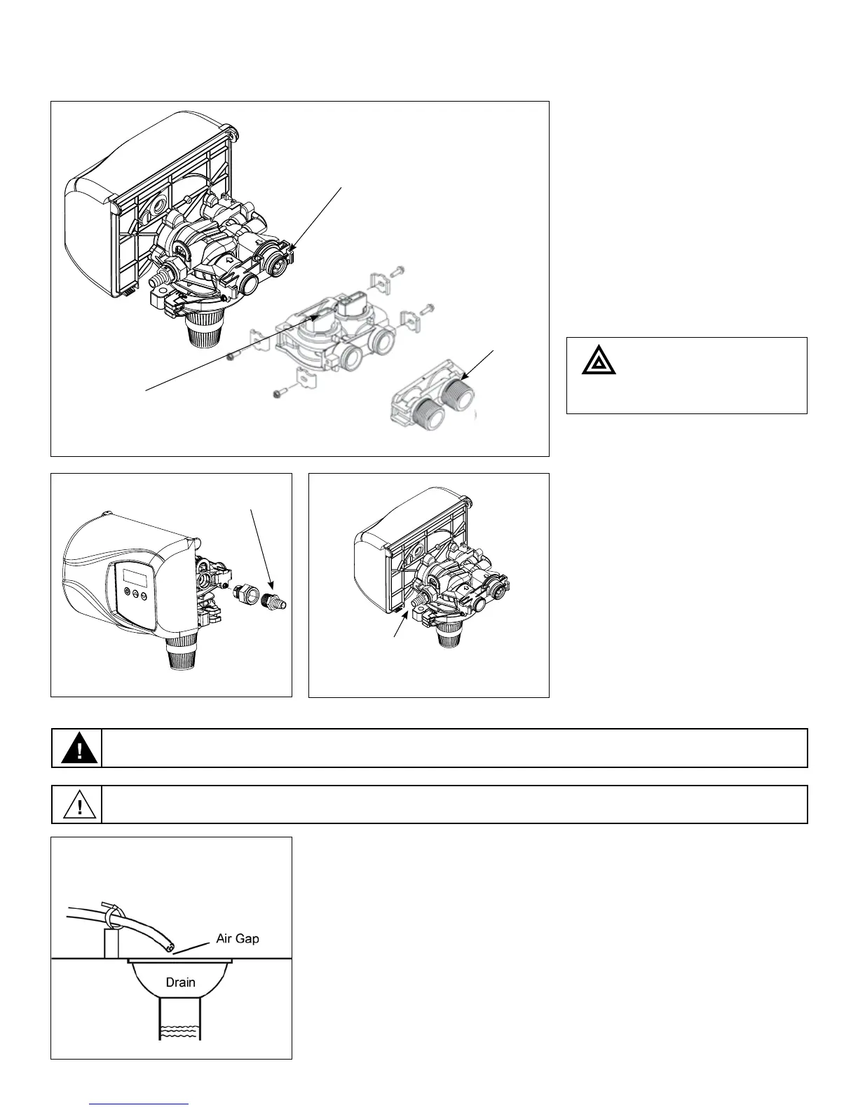
Do not use pipe thread
compound as it may
attack the material in
the valve body
.
Yoke
Bypass
Make sure that the flow
meter is connected to the
outlet of the valve.
Flow meter installation is
optional. The flow meter is
not supplied with the filter.
4
4. Attach the bypass valve to the con-
trol valve (and yoke if plastic bypass
is used). Connect the inlet and outlet
of the water softener to the plumb-
ing in the house. The control valve
must not be submitted to tempera-
tures above 43°C (110°F). When
sweat fittings are used, to avoid
damaging the control valve, solder
the threaded copper adapters to
the copper pipe and then, using
Teflon tape, screw the assembly into
the bypass valve.
Waste connections or drain outlet shall be designed and constructed to provide for connection to the sanitary
waste system through an air-gap of 2 pipe diameters or 1 inch (22 mm) whichever is larger.
Never insert drain line directly into a drain, sewer line, or trap. Always allow an air gap between the drain line and
the wastewater to prevent the possibility of sewage being back-siphoned into the conditioner.
5. Drain Line Connection: Using teflon
tape, screw the 1/2” hose barb into
the drain port in the valve. Attach
1/2” drain hose to the hose barb and
tighten securely with a hose clamp.
Run the drain line to a floor drain or a
laundry drain. Complete any neces-
sary plumbing.
Hose Barb
Connect 1/2”
drain hose (not supplied)
with a hose clamp here
5
5
5