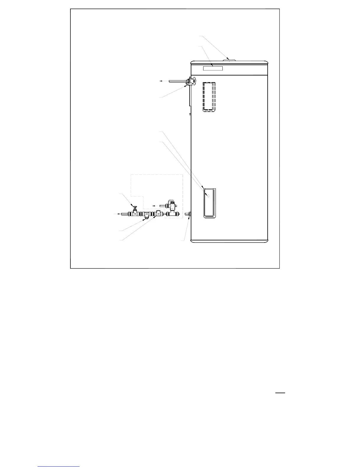
Figure 1: Installation Diagram
PRESSURE & TEMPERATURE RELIEF VALVE
The Pressure & Temperature relief valve is supplied loose with the water heater. The
valve rating is:
• 25 to 160L Models - 1400kPa
• 250 to 400L Models - 1000kPa
The relief valve must be installed directly into the top socket marked “RELIEF VALVE”.
The drain line from this valve must be installed in a continuously downward direction in a
frost free ambient position with the discharge end left open to atmosphere permanently.
The Pressure & Temperature Relief Valve supplied with the water heater is not sufficient to
enable connection of the water heater to supplementary energy sources such as solar
panels or slow combustion stoves (refer AS/NZS 3500.4.2 for guidance on these types of
installations)
Note: Plugs are supplied with the water heater to plug off the fittings that are not required.
Ensure that a sealing material is applied to the plugs for a leak tight fit.
ANODE ACCESS THROUGH PLUG
DATA PLATE
HOT WATER
OUTLET
TEMPERATURE
AND PRESSURE
RELIEF VALVE
DRAIN
ELEMENT COVER
TEMPERATURE ADJUSTMENT PLUG
(USER ADJUSTABLE MODELS ONLY)
EXPANSION VALVE ONLY
REQ'D WHERE LOCAL
REGULATIONS DEMAND.
DRAIN
ISOLATING VALVE
(SPINDLE VERTICLE)
COLD WATER
INLET
LINE STRAINER
NON RETURN VALVE
UNION CONNECTION
NOTE: A COMBINED ISOLATING VALVE/NON RETURN
VALVE/LINE STRAINER MAY BE USED
INSTALLATION DIAGRAM