7
RMO60TD Description
5 Description
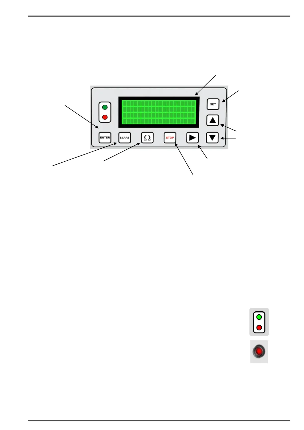
5.1 Front Panel Components
STOP
Press to stop a test or stop the alarm buzzer.
START
Press to start a test
Test parameters must be selected beforehand
Pressing START at the same time with SET allows you to go to setting menu for the language, time and
date settings.
Ω
Press to measure the resistance current value.
Press to measure the resistance value in TapC mode
Green LED
• Lights continuously when RMO60TD is turned on.
• Flashes when a test can be started.
• Flashes alternately with the red LED during a test.
Red LED
• Lights continuously in case of operational error.
• Lights continuously during discharging process.
• Flashes alternately with the green LED during the Current test.
• Flashes shortly during resistance measurement in the TapC test.
• Flashes alternately with the green LED during the TapC test.
Red LED - Discharge
• The red LED just above the red output connector remains lit until the accumulated energy of the
measured object is reduced to a harmless level
CAUTION
Within the period when the discharge LED lights it is prohibited to disconnect measuring cables.
The discharge diode cannot be switched off by pressing STOP.
ENTER button to
confirm the defined test
parameters, Language,
Time and Date
START button to
start the test
current.
Ω button to measure the
resistance current value and the
resistance and the ripple value in
TapC mode.
STOP button to stop a test, to
acknowledge the alarm buzzer and
return to the Curr menu.
RIGHT button to navigate in
the active menu
UP/DOWN buttons
to select a menu
and set test
parameters
SET button to
scroll between
Current menu,
TapC menu,
Dem menu and
the Memory
menu