24
Appendix B:
description of DVC-4000 auxiliary and power supply connectors
Auxiliary connector
The auxiliary connector on the DVC-4000 camera allows the user access certain camera control
and internal status signals. The following section describes each signal.
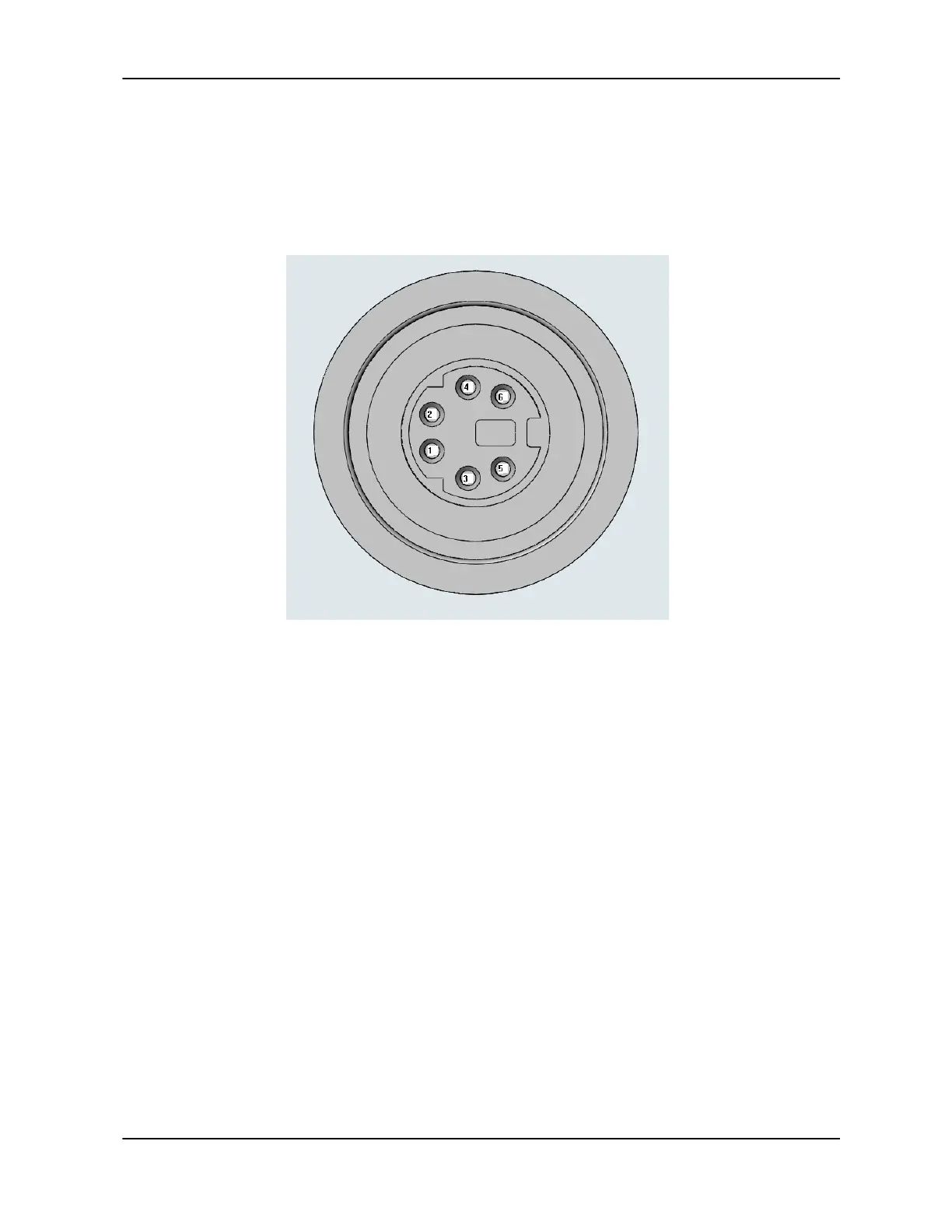
Illustration of the auxiliary connector on the rear of the DVC-4000 camera
Auxiliary Connector Pin Signal list:
Pin # Signal
------------------
1 ENL (Output)
2 DIFF_RESET_OUT (Output)
3 TTL_RESET (Input)
4 GND
5 ENF (Output)
6 STROBE/INT-PULSE (Output)
Pin 1, ENL
ENL refers to “Enable Line.” It is an active-high TTL signal and is asserted during the
valid pixel period on each line, as shown in the diagrams in Appendix A. It returns low
during the inter-line period between each line and during the inter-frame period between
each frame.
Pin 2, DIFF_RESET_OUT
This pin is an active-low TTL signal that is the buffered version of the CameraLink CC1
signal. The CC1 signal, driven from the host, is one of the software-controlled trigger
signals for the camera as described in Appendix A. The CC1 signal is brought out of the