9
English
Symbol Meaning
Do not dispose of the power
tool in a domestic waste
container.
DWT
power tool designation
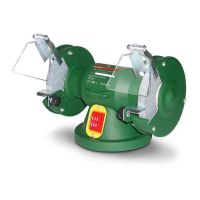
Double grinders are designed for different grinding and
sharpening works (removal of sharp edges, bevelling,
sharpening of cutting tools, etc.).
1
Power tool
components
Protective glass
2 Cover of protective housing
3 Grinding disc *
4 Protective housing
5 Supporting plate
6 Wing nut *
7 Base plate
8 On / off switch
9 Fasteners of supporting plate (lock washer,
washer, screw)
10 Fasteners of protective glass (nut, lock washer,
washer, screw)
11 Protective glass holder
12 Fasteners of protective glass holder (nut, lock
washer, washer, screw)
13 Fasteners of protective housing (nut, lock washer,
washer, screw)
14 Spindle
15 Flange
16 Gasket
17 Fastening nut of grinding disc
* Optional extra
Not all of the accessories illustrated or described
are included as standard delivery.
Installation and regulation
of power tool elements
Before carrying out any works on the power tool it
must be disconnected from the mains.
Do not draw up the fastening elements
too tight to avoid damaging the thread.
Follow precisely the sequence of parts
installation shown on the pictures.
Assembly / disassembly / adjustment of supporting
plate (see g. 1)
• Mount the supporting plate 5 using the fasteners 9
and wing nut 6 (see g. 1).
• During dismantling of supporting plate 5 repeat the
operations described above in reverse order.
• Adjust timely the distance between supporting
plate 5 and grinding disc 3, for this purpose loosen
wing nut 6 and move supporting plate 5 in the direction
of grinding disc 3. The distance between supporting
plate 5 and grinding disc 3 should not exceed 2 mm.
Assembly / disassembly / adjustment of protective
glass (see g. 2)
• Insert protective glass 1 in holder 11 and x it with
the use of fasteners 10 (see g. 2).
• Place holder 11 with inserted protective glass 1
on protective housing 4 and x it with the use of
fasteners 12 (see g. 2).
• During dismantling of holder 11 or protective
glass 1 repeat the operations described above in
reverse order.
• Adjust timely the distance between holder 11 and
grinding disc 3, for this purpose loosen nut and move
holder 11 in the direction of grinding disc 3. The
distance between holder 11 and grinding disc 3 should
not exceed 2 mm.
If the wear of grinding disc 3 is so
heavy that it does not allow adjusting
the distances between grinding disc 3
and supporting plate 5 or holder 11 it is
necessary to replace the grinding disc.
Installation / change of grinding disc (see g. 3-4)
After installation of the grinding disc and
before starting work make a trial start-up
switch on the power tool and let it idle
run for at least 5 minutes. It is prohibited
to use grinding discs that cause beats and
increased vibration of the power tool.
• Remove cover 2 and protective housing 4 as shown
on g. 3.
• Holding grinding disc 3 with one hand unscrew
nut 17 (see g. 4). Attention: nut 17 used to x the
left grinding disc has left-hand threading.
• Dismantle from spindle 14: ange 15, gasket 16,
grinding disc 3, gasket 16, ange 15.
• Clean all the parts by the soft brush and mount
on spindle 14: ange 15, gasket 16, grinding disc 3,
gasket 16, and ange 15. Attention: mount
anges 15 exactly as shown on g. 4, do not turn
them.
• Holding grinding disc 3 with one hand, screw
nut 17.
• Install protective housing 4 and cover 2.
• Fix the position of cover 2 with the help of
fasteners 13.
Initial operation
of the power tools
Always use the correct supply voltage: the power
supply voltage must match the information quoted on
the power tool identication plate.
Switching the power
tool on / off
Switching on:
Move switch 8 into the "On" position.
Switching off:
Move switch 8 into the "Off" position.
 Loading...