Do you have a question about the Dwyer Instruments DCT1010DC and is the answer not in the manual?
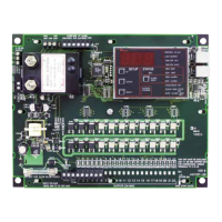
Details output channels, power requirements, fuse rating, temperature limits, on/off times, and weight for the DCT1000DC timer controller.
Provides detailed measurements for the DCT1000DC master controller and optional DCP100A pressure module.
Lists pressure ranges, temperature limits, accuracy, output signal, and alarm contacts for DCP100A/DCP200A modules.
Specifies the 10-30 VDC power supply requirement for the DCT1000DC and cautions against exceeding 35V.
Details Euro-style connector system for solenoids, power, and external switches, including wire gauge and strip length.
Explains using external pressure limit switches or sensors for on-demand cleaning via high/low limit inputs.
Describes connecting a manual override switch for continuous mode or periodic use via a SPST toggle switch.
Details connecting the down time clean terminal to common for a programmed run cycle of 0-255 minutes.
Explains daisy-chaining DCT1000DC boards for systems exceeding 22 channels, master/slave configuration.
Describes enabling continuous cleaning via jumper or manual override, controlled by time on/off and cycle delay.
Explains connecting the alarm relay contacts (TB5) for external alarm control when high alarm or low alarm thresholds are met.
Provides instructions and cautions for installing the DCP100A/DCP200A pressure modules, including alignment and locking pins.
Explains how to connect the alarm mode switch for auto alarm reset functionality, using a jumper or isolated contact switch.
Details connecting an external switch for alarm reset, which operates when pressure returns to normal and timeout expires.
Describes using the isolated 4-20 mA output for remote monitoring of differential pressure with external or internal power.
Details wiring an optional mode selection switch for continuous, on-demand, or off modes, including safety precautions.
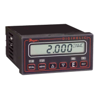
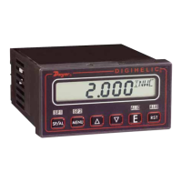
Explains using SELECT, UP, and DOWN buttons to navigate menus and adjust values on the master controller's display.
Configures the last activated channel, important for multi-module systems, with a default of the total number of channels.
Defines the solenoid activation delay period between 1 and 255 seconds. Factory default is 10 seconds.
Sets the solenoid firing duration in milliseconds, ranging from 10 to 600 msec in 10 msec increments.
Sets the pressure threshold for initiating the cleaning cycle when a pressure module is installed.
Sets the pressure threshold for ending the cleaning cycle when a pressure module is installed.
Configures the high alarm pressure threshold, indicating when an alarm condition is met.
Configures the low alarm pressure threshold, indicating when an alarm condition is met.
Sets a delay time between the end of one cleaning cycle and the beginning of the next, from 0 to 255 minutes.
Selects a duration from 0 to 255 minutes for forced cleaning mode when activated by a down time cycles input.
Sets the time delay, from 0 to 255 seconds, for auto alarm reset after pressure returns to normal and timeout expires.
Procedure to reset all controller parameters to original factory default values using UP and DOWN buttons.
Describes the power on LED, indicating proper operation of the power supply.
Explains the LED indicator for each channel, illuminating when the solenoid triac switch is active.
Details the indicator for master/slave communication status, showing system operation and communication checks.
Lists error codes displayed on the controller, their meanings, and required actions for troubleshooting.
| Model | DCT1010DC |
|---|---|
| Operating Temperature | 32 to 140°F (0 to 60°C) |
| Output Type | Analog |
| Mounting Orientation | Any |
| Type | Temperature Controller |
| Stability | ±0.5% FS/year |
| Humidity Range | 0 to 95% RH, non-condensing |
| Power Requirements | 12 to 30 VDC (24 VDC nominal) |
| Operating Voltage | 12 to 30 VDC (24 VDC nominal) |
| Output Signal | 4 to 20 mA |
| Electrical Connections | Screw terminal |
| Process Connections | 1/2" NPT |
| Port Connections | 1/2" NPT |