Modbus
®
Communications Protocol Overview
Modbus
®
Communications Protocol Functions
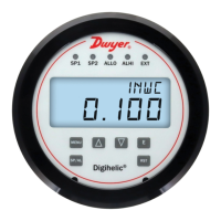
The DHC supports the following functions.
Modbus
®
Communications Protocol Registers
Input Registers
The String data type is read as a stream of ASCII characters with the rst character
sent in the MSB of the rst register and the second character sent in the LSB of the
rst register and so on. If the string is shorter than the allotted size, the remaining bytes
will be zero padded.
Holding Registers
Pressure/Velocity/Flow Units: The unit selected is independent of the display unit.
Alarm High/Low Limit Status: The alarm status can be reset to inactive by writing
inactive to the status register. This is allowed only if Manual Alarm Reset is Enabled
and the process value no longer satises the alarm condition. In all other cases a
Modbus
®
communications protocol error is returned.
INPUT REGISTERS
Register Description Data Type Range
0001-0002
0003-0004
0005-0006
0007-0008
0009-0010
0011
0012
0013
0014-0015
8001-8016
8017-8020
8021-8028
8029-8032
Pressure
Velocity
Flow
Peak
Valley
Set Point 1 Status
Set Point 2 Status
External Input Status
Error Flags
Model Number
Serial Number
Firmware Version
Date Code
32bit oat
32bit oat
32bit oat
32bit oat
32bit oat
16bit integer
16bit integer
16bit integer
32bit integer
String(32)
String(8)
String(16)
String(8)
-
-
-
-
-
0=Inactive, 1=Active
0=Inactive, 1=Active
0=Inactive, 1=Active
See Table Below
“DHC-XXX-XXX”
“XXXXX”
“X.X.X”
“XXXXXX
INPUT REGISTERS
Register Description Data Type Range
0001-0016
0017
0018
0019
0020
0021-0022
0023-0024
0025-0026
0027-0028
0029
0030
0031-0032
0033-0034
0035
0036-0037
0038-0039
0040
0041-0042
0043
0044-0045
0046
0047
0048
0049
0050
0051
0052
0053
0054
0055
0056
0057
0058
Device Name
Process Mode
Pressure Unit
Velocity Unit
Flow Unit
Velocity K-Factor
Flow Area
Process Output Low
Process Output High
Voltage Output Range
Set Point 1 Enable
Set Point 1 Trigger Value
Set Point 1 Reset Value
Set Point 2 Enable
Set Point 2 Trigger Value
Set Point 2 Reset Value
Enable Alarm High Limit
High Alarm Limit
Enable Alarm Low Limit
Low Alarm Limit
Manual Alarm Reset
Power Up Alarm Inhibit
Alarm Delay
Alarm High Limit Status
Alarm Low Limit Status
Relay 1 Source
Relay 1 Action
Relay 2 Source
Relay 2 Action
Enable External Input
External Input Type
External Input Activation
Delay
Damping Time
String(32)
16bit integer
16bit integer
16bit integer
16bit integer
32bit oat
32bit oat
32bit oat
32bit oat
16bit integer
16bit integer
32bit oat
32bit oat
16bit integer
32bit oat
32bit oat
16bit integer
32bit oat
16bit integer
32bit oat
16bit integer
16bit integer
16bit integer
16bit integer
16bit integer
16bit integer
16bit integer
16bit integer
16bit integer
16bit integer
16bit integer
16bit integer
16bit integer
“DHC”
0=Pressure, 1=Velocity,
2=Flow
0=inWC, 1=ftWC, 2=mmWC,
3=cmWC, 4=PSI, 5=inHG,
6=mmHg, 7=mBar, 8=Pa,
9=kPa, 10=hPa, 11=ozin
0=ft/min, 1=m/s
0=ft
3
/min, 1=m
3
/hr
0.001-9.999
0.125-25ft
2
(0.0116-2.3226m
2
)
-
-
0=0-10V, 1=0-5V, 2=1-5V,
3=2-10V
0=False, 1=True
-
-
0=False, 1=True
-
-
0=False, 1=True
-
0=False, 1=True
-
0=Disabled, 1=Enabled
0=Disabled, 1=Enabled
0-3600
0=Inactive, 1=active
0=Inactive, 1=active
0=Off, 1=Set Point 1, 2=Set
Point 2,
3=Any Alarm,
4=High Alarm Limit, 5=Low
Alarm Limit, 6=External Input
0=Direct, 1=Reverse
0=Off, 1=Set Point 1, 2=Set
Point 2,
3=Any Alarm,
4=High Alarm Limit, 5=Low
Alarm Limit, 6=External Input
0=Direct, 1=Reverse
0=False, 1=True
0=Normally Open,
1=Normally Closed
0-3600
0-30
Display Errors
Error Flags
Bit Position Description
EADR
ouEr
Undr
ER 1
ER 2
ER 3
ER 4
ER 5
ER 6
ER 7
0
1
2
3
4
5
6
7
8
9
Invalid Address
Over Range
Under Range
Sensor Range Exceeded
Sensor Error
No Sensor
User Settings Invalid
Factory Settings Invalid
External Memory Failure
Internal Memory Failure
Modbus
®
communications protocol installations should comply with
Modbus
®
Communication Protocol over Serial Line Specication
and Implementation Guide V1.02, Modbus
®
Organization, Inc., 2006
NOTICE
Communications wiring must be in a daisy-chain fashion. Star
connections and T connections are not permitted
NOTICE
www.calcert.com sales@calcert.com1.800.544.2843
0
5
10
15
20
25
30

 Loading...