Model
DFC Valve Actuator
Operation, Parts and Instruction Manuals
Dyna-Flo Control Valve Services Ltd.
Edmonton, Alberta, CANADA
Website: www.dynaflo.com
Phone: 780
• 469 • 4000
Toll Free: 1 • 866 • 396 • 2356
Fax: 780 • 469 • 4035
Instruction Manual May 2007
4
how to install the actuator on the valve. The actua-
tor must be installed on the valve before being
installed into the pipeline. Ensure that the travel
has been checked; refer to the “Bench Settin Actua-
tor” section (below) for detailed instructions on this
procedure.
Bench Setting Actuator
(Refer to Figure 3)
! CAUTION !
To prevent valve stem damage perform
the bench setting with actuator removed
from valve!
! CAUTION !
The following procedures must be com-
pleted before installing the stem connec-
tor (Key 22) between the actuator stem
(Key 3) and the valve stem (Key 31).
Except for the DFC Size 3220, the stem
connector assembly (Key 22) will need to
be installed to prevent the stem from
rotating while adjusting the bench set.
1 To properly verify bench setting 3 pieces of
information are required:
1 Upper Bench Set Loading Pressure
2 Lower Bench Set Loading Pressure
(example: on a 10-30 Psig bench set, 10
is the lower and 30 Psig is the upper)
3 Travel
This information is available on the actuator
name plate (Key 33). If information is missing
or incomplete contact your Dyna-Flo Sales
Office.
2 Before applying pressure to the actuator make
sure that the spring (Key 2) is properly seated
onto the spring seat (Key 20) (not required on
a new factory assembled actuator).
3 Connect a supply line with a gauge that can
accurately measure both 0 Psi and the upper
bench set pressure.
4 Apply maximum casing pressure to the
actuator to verify seal integrity is good. Use a
soapy and solution to check for any air leaks
from the lower casing gasket (Key 13) and the
diaphragm (Key 7). On a new actuator this will
have been done a tthe factory and won’t be
required.
Unpacking
Check the Packing List against materials recieved,
while unpacking the actuator. The Packing List
describes actuator and accessories in each shipping
container.
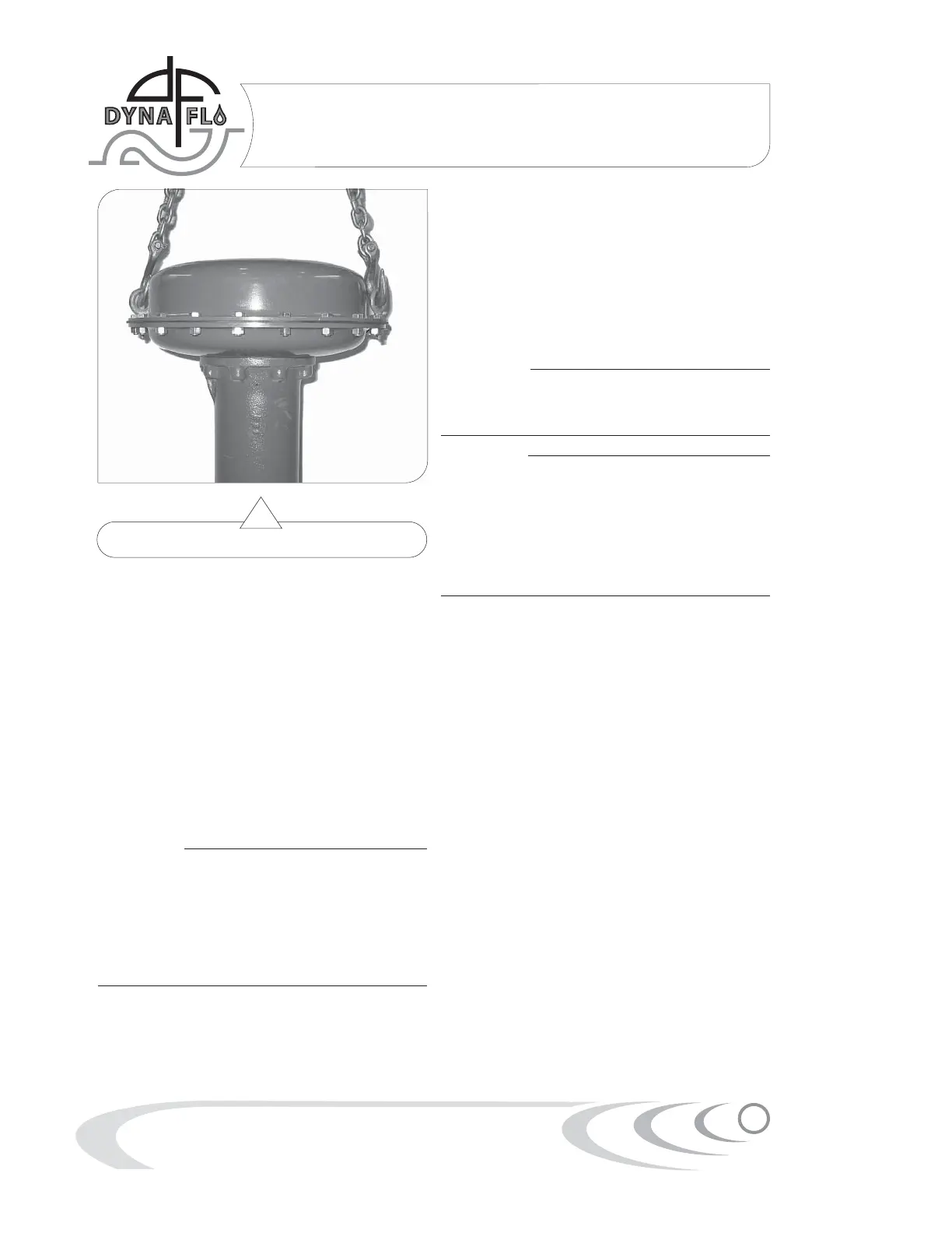
When lifting the actuator from the shipping contain-
er, it is advisable to remove 2 actuator casing bolts,
180
o
apart, and temporarily replace them with eye
bolts and nuts. Position the lifting straps through
the eye bolts to avoid damage to the tubing and
mounted accessories. See Figure 3.
Installation
! CAUTION !
Do not use an operating pressure that
exceeds the Maximum Diaphragm Casing
Pressure (See Table 1). Also make sure
that the operating pressure does not
create a force on the actuator stem that is
greater than the Maximum Allowable Out-
put Thrust (See Table 1)!
If the actuator has been installed on the valve in
the factory, the assembly is ready to be placed
inline. Refer to the proper Dyna-Flo valve manual
for installation. Refer to the “Mounting: Actuator to
Valve” section (Page) for detailed instructions on
Figure 2 Rigging Setup
 Loading...