Dyna-Flo Control Valve Services Ltd.
Edmonton, Alberta, CANADA
Website: www.dynaflo.com
Phone: 780
• 469 • 4000
Toll Free: 1 • 866 • 396 • 2356
Fax: 780 • 469 • 4035
Model
DFC Valve Actuator
Operation, Parts and Instruction Manuals
Instruction Manual May 2007
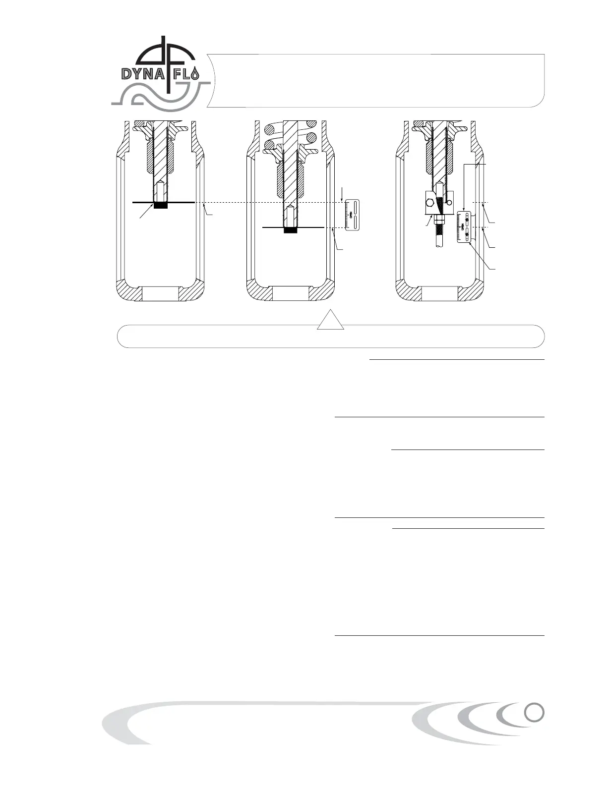
5
Rated Valve
Travel Scale
(Key 24)
Mark Upper
Bench Set
Loading
Pressure
Mark Lower
Bench Set
Loading
Pressure
Magnet/Ruler
Combination Setup
Travel
Indicator
Disk
(Key 27)
Travel Scale Adjusted
To Coincide With The
Travel Of The Travel
Indicator Disk After
Actuator Has Been
Mounted To Valve
Lower Bench
Set Loading
Pressure Mark
Upper Bench
Set Loading
Pressure Mark
*Note: Distance
of Travel Should
Match Specification
Given on Name Plate
(Key 33)
Figure 3 Bench Set Spring Adjustment Diagram
For Push Down to Close Valves
1 Apply the upper bench set loading pressure
plus 5 Psi (34 kPa) to the actuator and note
where stem travel stops, this should occur
when the travel stop (Key 10) encounters the
upper casing (Key 5). The intent is for the travel
stop to contact the upper casing at the exact
time the upper bench set loading value is
reached. Apply 5 Psi (34 kPa) above and below
the upper bench set value to verify this.
(Example: for a 10-30 bench set the travel stop
should contact the upper casing at exactly 30
Psig) If stem (Key 3) travel stops before or
after the upper bench set value, the spring
adjuster (Key 21) will need to be adjusted to
obtain the proper bench set. You may need to
relieve pressure to the actuator in order to
adjust the spring adjuster. Turning the spring
adjuster up (towards the top of the actuator)
will increase the bench set pressure.
2 Once the upper bench set pressure has been
set, use a magnet or piece of tape to attach
a piece of metal or ruler to the bottom of the
actuator stem (Key 3) to use as an indicator
arm. Make a mark to indicate the stem position
at the upper bench set pressure (See Figure 3).
Make sure the travel is fully extended.
3 Adjust the gauge to the lower bench set
pressure and mark the actuator stem position.
The measurement between the upper and
lower bench set marks should equal the travel
indicated on the name-plate within 1/16” (1.6 mm).
! Note !
If these steps do not allow you to reach
the proper bench set pressure then an
incorrect or damaged spring may be the
problem. Contact your Dyna-Flo Sales
Office for more information.
Mounting: Actuator to Valve
! CAUTION !
During mounting the actuator stem and
valve stem could come into contact with
each other. Ensure that the valve stem is
pushed down before trying to install the
actuator, doing this will help to protect
the stem threads from getting damaged.
! CAUTION !
It may be necessary to apply loading
pressure to the actuator temporarily to
move the actuator stem and allow for
more clearance between it and the valve
stem. Use extreme caution when moving
the pressurized actuator; ensure that no
clothing, hair, hands or tools come in
between the two stems or moving parts.
If loading pressure fails personal injury or
property damage may occur.
1 Make sure the valve is securely supported
using a vice or similar method before proceed-
ing. It is advised to place valve on a surface
that will be able to support the combined
weight of valve and actuator.
 Loading...