Model
DFC Valve Actuator
Operation, Parts and Instruction Manuals
Dyna-Flo Control Valve Services Ltd.
Edmonton, Alberta, CANADA
Website: www.dynaflo.com
Phone: 780
• 469 • 4000
Toll Free: 1 • 866 • 396 • 2356
Fax: 780 • 469 • 4035
Instruction Manual May 2007
6
Mounting: Actuator to Valve
(cont’d)
2 Make sure the stem is pushed down away from
the actuator. Thread the two nuts (Keys 28 &
29) all the way onto the valve stem. Install the
travel disk (Key 27) onto the valve stem
(concave side down) so that it rests on the jam
nuts. Note: with the travel disk on the stem it
may not be possible to mount the actuator
because the travel disk will not slide through
the yoke boss mounting area. Before attempt-
ing to mount the actuator check to see that the
disk will go through the yoke boss mounting
area. If not, the travel disk will need to be
inserted on the stem after the yoke nut (Key
27). Place the travel disk overtop of the yoke
nut during the yoke nut installation process.
3 Be sure to have the yoke nut (Key 32) sitting
inside the actuator yoke or have the yoke nut
ready to be placed in between the actuator
stem and valve stem when lowering the
actuator onto the valve. Carefully lift and lower
the actuator onto the valve, this may require
more than one person or a heavy lifting device.
Once on the valve, orientate the actuator to be
properly aligned parallel with the valve body
(see Figure 5).
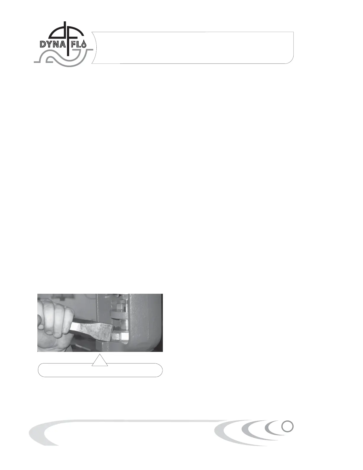
4 Thread the yoke nut onto the valve bonnet and
tighten using a heavy blunted chisel and
hammer until the yoke is secured tightly to the
valve (Refer to Figure 4). DO NOT OVER
TIGHTEN.
Stem Connector Installation
1 Apply upper loading pressure plus 5 Psi (34
kPa) to the actuator if loading pressure was not
applied prior to mounting. This should put the
the actuator in the fully up position.
2 Install the travel scale (Key 24) to the actuator
using the speed nuts (Key 26) and machine
screws (Key 25). Position the travel disk (Key 27)
on top of the jam nuts at the bottom of the
travel scale (Key 24) by adjusting the jam nuts
(Keys 28 & 29). Carefully move the plug / stem
up until the travel disk indicates full travel as
indicated on the travel scale. The movement of
the plug / stem must be done with caution not
to damage the stem.
3 As shown in Figure 3, the valve stem should fit
inside the actuator stem. Install the stem
connector (Key 22). It is important to position
the stem connector so that the threads
properly engage with those of the stems.
Connect the other half of the stem connector
and orientate the stem connector as show in
Figure 3. It is at this time that any accessories
(such as positioner arms) that need to be
connected to the stem connector should be
put in place. Install the stem connector bolts
and tighten.
4 Re-position the travel disk (Key 27) under the
stem connector (Key 22), thread up the jam
nuts (Keys 28 & 29) to hold the travel disk in place
and tighten the jam nuts together (Refer to
Figure 3). Do not over tighten the jam nuts.
5 Apply pressure and stroke the valve several
times. Loosen the travel scale (Key 24) and
reposition it to align with the closed position of
the valve and verify that the travel is still
accurate to the value indicated on the name
plate (Key 33). If travel is inaccurate it may be
necessary to repeat the stem connector
procedures or to refer back to Bench Setting
Actuator.
Figure 4 Yoke Nut Tightening
 Loading...