Dyna-Flo Control Valve Services Ltd.
Edmonton, Alberta, CANADA
Website: www.dynaflo.com
Phone: 780
• 469 • 4000
Toll Free: 1 • 866 • 396 • 2356
Fax: 780 • 469 • 4035
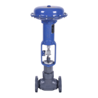
Model
DFC Valve Actuator
Operation, Parts and Instruction Manuals
Instruction Manual May 2007
7
Maintenance
! WARNING !
Disconnect all power lines and pneumatic
lines making sure the actuator is depres
surized prior to commencing disassembly.
Remove any power source that may cause
the actuator to spontaneously move. Also,
relieve any spring pressure or compres-
sion before you start the disassembly
process, this can be done by lowering the
spring adjuster (Key 21).
! CAUTION !
Use bypass valves or completely shut off
process media to isolate the valve from
the process pressure and fluids. Relieve
process pressure and drain process media
from both side of the valve.
Actuator Disassembly
1 Make sure that the valve and actuator are
securely supported and that valve body is
clamped in place and unable to move during
disassembly.
2 Completely remove spring compression by
turning the spring adjuster (Key 21) until
loose. Once spring compression is removed
disassemble the stem connector (Key 22) and
remove both halves. Inspect all the threads on
both halves of the stem connector and make
sure there is no damage.
3 If removal of the actuator from the valve is
necessary, the yoke nut (Key 32) will need to be
completely loosened. Using a heavy blunted
chisel and hammer, completely loosen the yoke
nut (Key 32) (Refer to Figure 4). Note: the yoke
nut will not be able to be removed until the
actuator is lifted from the valve (Refer to Un-
packing and Mounting sections for actuator
hoisting instructions).
4 Before work begins make sure that the
actuator is secured in place and properly
supported.
Spring removal
1 Unscrew the spring adjuster (Key 21) and
remove it from the actuator stem. With the
spring adjuster removed it is possible to re
move the spring seat (Key 20) from the yoke
(Key 1). Inspect the threads of the spring
adjuster and for damage and corrosion. Also,
inspect the spring.
Upper Diaphragm Casing Disassembly
1 Remove all the diaphragm casing cap screws
(Key 18) and nuts (Key 19). Lift the upper
diaphragm casing (Key 5) from the actuator.
2 From the top of the open actuator remove the
hex head bolt (Key 11) and travel stop (Key 10).
The actuator stem (Key 3) may rotate
during hex head bolt removal, it may be
necessary to hold the stem or tap the wrench
with a hammer to loosen the bolt. Use extreme
caution and avoid damaging the actuator stem
during this process. Remove the stem from the
yoke mounting end.
3 Being careful not to damage the actuator stem
(Key 3) remove it from the actuator. Inspect
the actuator stem for thread damage, deep
scratches and corrosion. Minor scratches and
corrosion can be polished out (scratches that
will not stop your fingernail are considered
minor), if there are deep scratches, corro-
sion or damage the actuator stem will need to
be replaced.
4 Remove the upper diaphragm plate (Key 8)
from the actuator and diaphragm (Key 7),
inspect the plate for cracks and wear. Note: on
older actuators the upper diaphragm plate
maybe composed of two separate pieces.
Inspect the diaphragm for tears, abnormal
stretching, cracks and pliability. If the dia-
phragm is brittle, torn or cracked it will need to
be replaced.
5 Remove the lower diaphragm plate and inspect
it for any cracks, wear or corrosion.
6 Using a pair of pliers or other tool, remove the
snap ring (Key 14) from the yoke (it sits overtop
of the bushing (Key 15). Replace if necessary.
 Loading...