Dyna-Flo Control Valve Services Ltd.
Edmonton, Alberta, CANADA
Website: www.dynaflo.com
Phone: 780
• 469 • 4000
Toll Free: 1 • 866 • 396 • 2356
Fax: 780 • 469 • 4035
Model
DFC Valve Actuator
Operation, Parts and Instruction Manuals
Instruction Manual May 2007
9
Maintenance
(cont’d)
Upper Diaphragm Casing Assembly
1 Place the lower diaphragm plate (Key 6) into
the lower diaphragm casing (Key 4) and onto
the actuator stem (Key 3) as shown in
Figure 7. Insert the diaphragm (Key 7) into the
lower casing over the lower diaphragm plate
and align the holes on the diaphragm with
those of the lower casing.
2 Install the upper diaphragm plate (Key 8) onto
the actuator stem so that it rests in the dia-
phragm (for a two piece diaphragm plate
design both parts of the plate will need to be
installed Figure 6 Key 9).
3 Place the travel stop (Key 10) over the actuator
stem so that it rests on the upper diaphragm
plate. Coat the threads of the hex head bolt
with anti-seize and thread it into the top of
the actuator stem (Key 3), tighten the hex
head bolt completely making sure that the
holes on the diaphragm still align with those of
the lower casing (Refer to Torque Chart on
Page 11).
4 Lift and place the upper diaphragm casing (Key
5) onto the top of the actuator, make sure that
the holes of the upper casing align with those
of the lower casing (Key 4) and diaphragm
(Key 7). Install the casing cap screws (Key 18)
into the casings, Do Not coat the cap screws
with anti-seize. Thread the nuts (Key 19) onto
the casing cap screws, Do Not over tighten the
cap screws refer to Torque Chart on Page 11.
Tighten the casing cap screws in a crisscross
pattern to half required torque and in the
same pattern completely tighten cap screws to
full torque. In a circular pattern re-tighten the
casing cap screws (Key 18) to full torque.
5 Refer to Bench Setting Actuator portion of
manual to complete the actuator assembly.
32
33
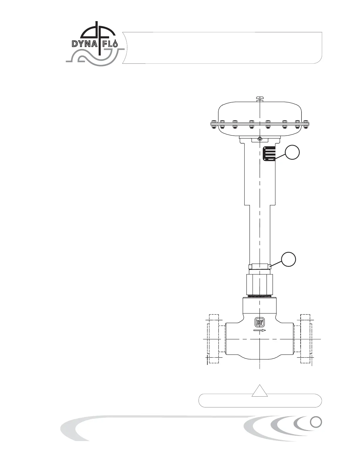
Figure 5 Actuator & Valve Mounting Diagram
 Loading...