Manual 36532 DYNA 70025 Integrated Actuator
QCC LLC 3
Preliminary Set-Up Procedure
The following method will properly set up the mechanical governor for operation
with the electronic integrated actuator. Proper calibration of both the mechanical
and electronic governor must be performed in order for the system to operate
properly. Failure to perform this procedure properly may result in inability to
provide maximum power or cause poor steady state speed control.
CAUTION: Perform Steps 1 thru 3 PRIOR to starting the engine.
1. Position the shut-off shaft assembly (if equipped with one) in the “Fuel
On” position by rotating it in the direction shown in Figure 6 until it
reaches its limit of travel. Secure the shut-off shaft assembly in place with
existing mechanical linkage. A spring may be used to hold it in place
when there is no linkage.
CAUTION: Do not attach springs to the engine’s high-pressure lines.
2. Throttle shaft assemblies are often locked in the “High Idle” position on
pumps equipped with speed droop governors. When this is the case, the
low idle screw may be backed out a maximum of three (3) turns. This
should only be done if the high idle speed is known to be greater than
12% above the rated speed. Excessive backing out of the low idle screw
may result in the disengagement of the pump’s internal components.
WARNING
This procedure must be followed carefully in order to not overspeed
the engine and cause damage to the generator or other load.
3. Adjust the droop by turning the droop adjusting screw in a counter-
clockwise (CCW) direction until it stops. See Figure 6. Some pumps
may not be equipped with a speed droop adjustment.
Turn the droop adjusting screw clockwise (CW) two full turns. The
mechanical governor is now set in a position that will permit starting the
engine to calibrate the electric integrated actuator governor. Do not
operate the engine without the electronic governor connected and the
system calibrated properly as described in the calibration chapter.
Once this droop adjustment has been made, do not readjust.
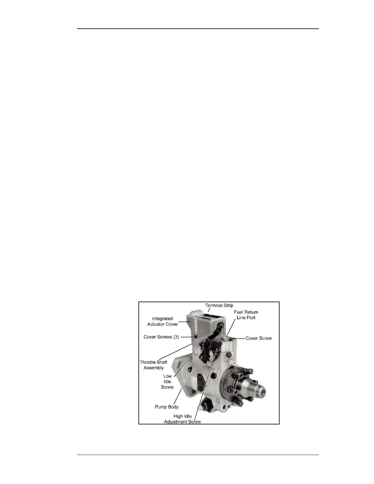
Figure 6