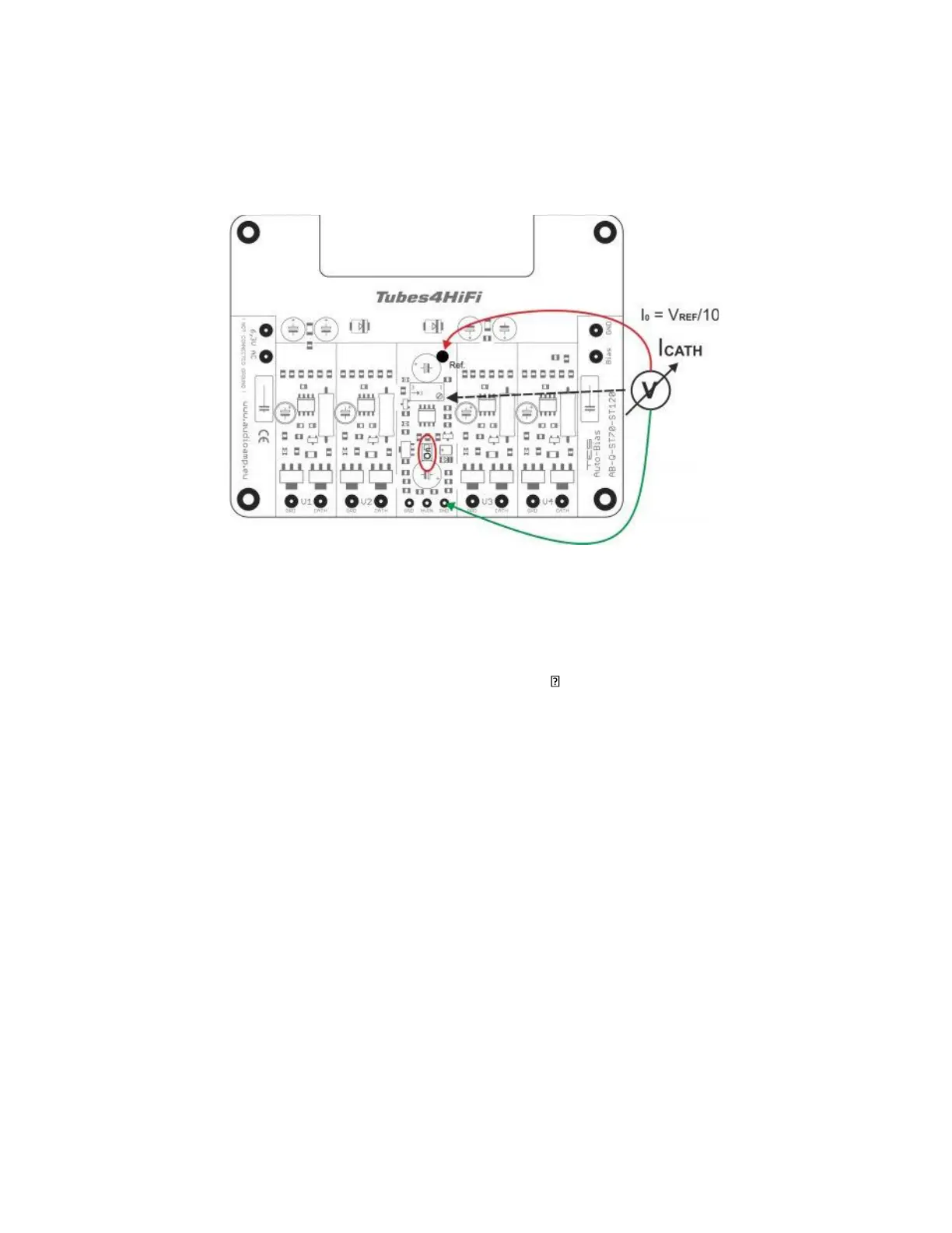
That’s it, you just set the AB-Q module to the desired bias operating level. For EL34 Vref= 0.380V. It is set
without signal.
Keep all of the above wires neat and tidy, maybe use zip ties to group them.
This now pretty much completes the wiring of the AB-Q module to the ST70 driver PC-3 pcb and the
power tubes.
Double check all the wiring steps again, even triple check them
Once you are confident that all your wiring is correct and as per the above steps, it is time to test your
AB-Q module installation. We are assuming that you have installed the AB-Q module into a known
working ST70, not a brand new ST70, as you would need to carry out a different sequence of testing your
ST70 before you should power up the AB-Q module.
Plug in all tubes, that is the driver tubes, power tubes and the tube rectifier.
Maybe stick a piece of styrofoam under one of the output transformers to cradle the ST70 chassis so that
the tubes do not touch the bench top.
Connect an 8 OHM dummy load of at least 100W capacity or your speaker and if you can, short the input
using a dummy RCA plug.
Power up your amp. The red LED on the AB-Q module should come on straight away and will go out after
about 20s.
After an additional 40 to 50s, each of the blue LED’s on the AB-Q module should start to come on, which
indicates that each output tube has reached the preset bias level and all is good. Excellent!
You can measure the actual bias voltage on each output tube with a meter just to double check.
Set you volt meter to the 1V, 2V or 5V scale in DC volts. Put the red meter lead on pin 1/8 on a power
tube socket, V 2,3 ,V 6,7 and place the black meter to the chassis star ground tag. The meter should read
close to 0.380V/380mV if EL34’s are used. This reading might be a little higher to start with and will get
close to or exactly to the preset bias voltage as the output tubes warm up.
Do this measurement for each output tube, V2, 3, 6 and 7 , measuring at pins 1/8.
Leave the amp running for about 10 minutes, all four of the blue LED’s should remain lit.