EasyManua.ls Logo

Dynalco SPD-100 - User Manual

Dynalco SPD-100
2 pages
Print Icon
To Next Page IconTo Next Page
Loading...
3211 Fruitland Ave
Los Angeles, CA 90058
SPD-100 & SPD-100L
SIGNAL-POWERED
TACHOMETER
Calibration Manual
Rev. B
P/N: 145F-12040
PCO 00010648
(c) Copyright 2017, Barksdale, Inc.
All Rights Reserved
REVISED: AUG 16, 2017
IMPORTANT PLEASE READ BEFORE
PROCEEDING!
The Dynalco SPD-100 & SPD-100L Tachometers are
designed for reliable and rugged operation. These
products have been designed and tested to meet the
demands required in many industrial locations.
Performance of this product is directly related to the
quality of the installation and knowledge of the user in
operating and maintaining the instrument. To ensure
continued operation to the design specifications,
personnel should read this manual thoroughly before
proceeding with installation, operation and maintenance
of this instrument. If this product is used in a manner not
specified by Dynalco, the protection provided by it may be
impaired.
Dynalco® is a Barksdale® brand.
WARNING
Failure to follow proper instructions may cause any one of the
following situations to occur: Loss of life; personal injury;
property damage; damage to this instrument; and warranty
invalidation.
For clarification of instructions in this manual or assistance
with your application, contact Dynalco as below:
Tech Support: Technical-dynalco-support@barksdale.com
or 1-866-227-8528
Customer Care: Sales-Dynalco@barksdale.com
or 1-800-835-1060
Or by mail:
Barksdale Inc.
Barksdale® and Dynalco® Products
3211 Fruitland Ave
Los Angeles, CA 90058
Follow all warnings, cautions, and instructions marked on and
supplied with the product.
Use only qualified personnel to install, operate, program and
maintain the product.
Educate your personnel in the proper installation, operation,
and maintenance of the product.
Install/calibrate equipment as specified in the
installation/calibration section of this manual. Follow
appropriate local and national codes. Only connect the product
to power sources and end devices specified in this instruction
manual.
Any repair is only to be performed by Dynalco using factory
documented components. Tampering or unauthorized
substitution of parts and procedures can affect the
performance and cause unsafe operation of your process.
All equipment doors must be closed and protective covers
must be in place unless qualified personnel are performing
maintenance.
Question and Answer IconNeed help?

Do you have a question about the Dynalco SPD-100 and is the answer not in the manual?

Summary

Important Information and Safety

Important - Please Read Before Proceeding!

Provides essential guidance on product operation, installation, and maintenance for optimal performance and safety.

General Safety Warnings

Details critical safety precautions to prevent injury, death, property damage, and warranty voidance.

Calibration Instructions

Calibration Procedure Steps

Step-by-step guide for calibrating the SPD-100/SPD-100L tachometer including signal input and adjustment.

Signal Frequency and Gate Time Calculations

Provides formulas and examples for calculating signal frequency and determining the correct gate time.

Gate Time Range Selection

Instructions for selecting the appropriate gate time range using the 4-position switch.

Optional On-Engine Calibration Method

Details an alternative calibration method using on-engine components and precise digital tachometers.

Overview

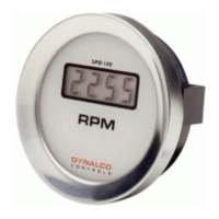
The Dynalco SPD-100 and SPD-100L are signal-powered tachometers designed for reliable and rugged operation in various industrial environments. These devices are factory-calibrated to customer-specified parameters, including the number of sensing teeth or discontinuities, sensing speed, and desired numerical display. They are designed to meet the demands of many industrial locations and their performance is directly related to the quality of installation and the user's knowledge of operation and maintenance.

Function Description:

The primary function of the SPD-100 and SPD-100L tachometers is to measure and display rotational speed (RPM). They are signal-powered, meaning they derive their operational power from the input signal itself, eliminating the need for an external power supply for the main display function. The SPD-100L model includes a lighted display, which requires an external 20 to 30 Vdc power source connected to terminals A and B. A dimming control feature is available for the SPD-100L, allowing for 0-100% lighting control, typically by connecting a 2 k Ohm, 2 Watt potentiometer (optional) to terminals A and B.

Important Technical Specifications:

  • Model Numbers: SPD-100 and SPD-100L
  • Manufacturer: Dynalco (a Barksdale brand)
  • Input Signal: Magnetic pickup output (connected to terminals 1 & 2).
  • Display: Digital display showing RPM.
  • Power Source (SPD-100L only for lighted display): 20 to 30 Vdc. For 32 Vdc systems (26-40 Vdc), an external 500 Ohm series resistor (1/2 Watt minimum) is required.
  • Gate Time Ranges (selectable via 4-position switch):
    • Position 1: 0.26-0.72 seconds
    • Position 2: 0.72-1.43 seconds
    • Position 3: 1.43-2.85 seconds
    • Position 4: 2.85-5.70 seconds
  • Calibration Controls: Located under a sealing plug on the back of the housing, these include a 4-position switch for gate time range selection and a vernier potentiometer for fine adjustment of the display reading.
  • Dimensions: Approximately 3.34 inches (8.5 cm) in diameter for the main body, with a total depth of about 3.77 inches (9.6 cm) including terminals. The mounting flange is approximately 3.6 inches (9.0 cm) wide.
  • Terminal Connections:
    • Terminals 1 & 2: Magnetic pickup input (no polarity).
    • Terminals A & B: Power input for SPD-100L lighted version (20-30 Vdc).

Usage Features:

  • Signal-Powered Operation: The SPD-100 does not require an external power source for its primary function, making it suitable for applications where external power is limited or undesirable. The SPD-100L, while signal-powered for its core function, requires external DC power for its lighted display.
  • Calibration Flexibility: The device can be calibrated in the field using a signal generator or by an on-engine method.
    • Signal Generator Method: Involves applying a calculated signal frequency to terminals 1 and 2, selecting the appropriate gate time range on the 4-position switch, and then adjusting the vernier potentiometer to achieve the desired display.
    • On-Engine Method: Involves connecting the magnetic pickup output to terminals 1 & 2, selecting the appropriate gate time range, and adjusting the vernier potentiometer until the display matches a known, precise digital tachometer.
  • Gate Time Calculation: The manual provides clear instructions for calculating the appropriate gate time based on the desired RPM and the signal frequency (RPM x Teeth or Discontinuities / 60). This allows users to precisely configure the tachometer for their specific application.
  • Vernier Potentiometer: This control allows for fine-tuning of the display reading. Turning it clockwise increases the display reading, while turning it counterclockwise decreases it.
  • Robust Design: Designed for reliable and rugged operation in industrial environments.

Maintenance Features:

  • Qualified Personnel: Installation, operation, programming, and maintenance should only be performed by qualified personnel.
  • Adherence to Instructions: Users are advised to read the manual thoroughly before proceeding with installation, operation, and maintenance to ensure continued operation to design specifications and to prevent impairment of the protection provided by the device.
  • Local and National Codes: Installation and calibration must follow appropriate local and national codes.
  • Authorized Repairs: Any repair must be performed by Dynalco using factory-documented components. Unauthorized substitution of parts or procedures can affect performance and potentially lead to unsafe operation.
  • Protective Covers: All equipment doors must be closed and protective covers must be in place unless qualified personnel are performing maintenance.
  • Troubleshooting Support: For clarification of instructions or assistance with applications, users can contact Dynalco's Tech Support via email (Technical-dynalco-support@barksdale.com) or phone (1-866-227-8528). Customer Care is also available (Sales-Dynalco@barksdale.com or 1-800-835-1060).
  • Warranty: Failure to follow proper instructions can lead to warranty invalidation. Using the product in a manner not specified by Dynalco may impair the protection provided and could result in property damage, instrument damage, or personal injury.

The Dynalco SPD-100 and SPD-100L tachometers are essential tools for monitoring rotational speed in industrial settings, offering precision, durability, and user-friendly calibration options.

Dynalco SPD-100 Specifications

General IconGeneral
BrandDynalco
ModelSPD-100
CategoryMeasuring Instruments
LanguageEnglish

Related product manuals