Input Filter Time
Constant
Off or 0.5 to 100.0 secs
.
Alarm Filter time
Constant
0.5 to 100.0 secs
.
Input fail Mode
When input fails PV should go
Low or High scale reading
Process Variable
Offset
Span of controller
.
Raw PV value
Linear input value, un-scaled (mA, mV or VDC)
High Alarm 1
Alarm 1 value, adjustable within
scaled range, in display units
Max
Low Alarm 1
Min
Alarm 1
Hysteresis
1 LSD to full span in display
units on safe side of alarm
High Alarm 2
Options as for alarm 1
Max
Low Alarm 2
Min
Al 2 Hysteresis
Scaling
Breakpoint 1
Multi-point scaling breakpoint 1
value, adjustable from to
in % of span
Display Value 1
Value to be displayed at multi-
point scaling breakpoint 1, in
display units
Range Max
Scaling
Breakpoint 2
Multi-point scaling breakpoint 2, adjustable up to
100% of span. Must be > value
Display Value 2
Value to be displayed at Multi-point scaling
breakpoint 2, in display units
Scaling
Breakpoint 3
n
Multi-point scaling breakpoint n..9, adjustable up to
100% of span. Must be >n value
Display Value 3
n
Value to be displayed at Multi-point scaling
breakpoint n..9, in display units
Tare Feature
Enables or disables the
input auto-zero Tare
feature
Setup Lock Code
to
Note: Operator mode screens follow, without exiting from Setup mode.
5. STRAIN GAUGE CALIBRATION MODE
Note: Configuration must be completed before adjusting Calibration parameters.
First select Calibration mode from Select mode (refer to section 2). Press to scroll
t through the parameters (while this key is pressed, and for 1 sec after, the parameter
legend is shown, then the current value). Press or to change the value.
To exit from Calibration mode, hold down and press to return to Select mode.
Note: Calibration mode will only be displayed if input type is set to
Parameter
Legend
for 1 sec
followed
by
Set Value Adjustment Range &
Description
Default Value
Mode Default
Enables or Disables
Defaulting of Values within
Mode
Shunt Resistor
Enables or Disables use of
shunt resistor
Calibration
Resistor Value
40% to 100% (appears only when
is)
Start Low
Calibration
Press and to start calibration
.
Start High
Calibration
Press and to start calibration
making sure to apply the high range
signal if is set
(Can only be accessed once a succesful
low cailbration has been completed)
Calibration Lock
Code
to
When the calibration procedure begins appears on the screen. Once
Calibration is complete appears on screen.
If there are any Faults with the calibration an error message will appear either
or .
means the low calibration will fail if the offset is less than -10mV or
greater than +10mV. This signifies potential faulty sensors or the high
calibration will fail if the count value is less than +20mV or greater than
+50mV. This signifies potential faulty sensors
means the high calibration will fail if the mV value is within 10mV of the
low calibration value. This is a potential RCAL failure.
6. SPECIAL MODE
Note: Configuration must be completed before adjusting Special parameters.
This mode enables special features with the correct code entered; enter a value of 0 as
default other wise please refer to your supplier for information on what special features
are available and which numbers invoke these
7. MESSAGES & ERROR INDICATIONS
These messages indicate that the instrument may require attention, or there is a problem
with the signal input connection. The message legend is shown for 1 second, followed by
its value.
Caution: Do not continue with the process until the issue is resolved.
Parameter
Legend
for 1 sec
followed
by
Value Description
Instrument
parameters are in
default conditions
Configuration & Setup is required. This screen
is seen at first turn on, or if hardware
configuration is changed. Press to enter
Configuration Mode, next press or to
enter the unlock code,
then press to proceed
Input Over Range
Input signal is > 5% over-range
Input Under Range
Input signal is > 5% under-range
(>10% under-range for 4 to 20mA, 1 to 5V and
2 to 10V
ranges)
Input Sensor Break
Break detected in input signal sensor or wiring
Option 1 Error
Option 1 module fault
Option 2 Error
Option 2 module fault
Option 3 Error
Option 3 module fault
Calibration
Shunt Resistor is Faulty
Calibration
High and Low calibration points are too close to each
other for a valid reading
Note: , or may also be displayed if an incorrect input
type is selected.
8. OPERATOR MODE
This mode is entered at power on, or accessed from Select mode (see section 2).
Note: All Configuration mode and Setup mode parameters must be set as
required before starting normal operations.
Press to scroll through the parameters (while this key is pressed, and for 1 sec
after, the parameter legend is shown, followed by the current value).
Note: All Operator Mode parameters in Display strategy 6 are read only (see
in configuration mode), they can only be adjusted via Setup mode.
Legend
for 1 sec
followed
by
Value
Display Strategy and
When Visible
Description
PV
Value*
Always
Process Variable value
Read only
Latched outputs can be reset
Mm
Max PV
Value
Strategies , , , , &
Maximum displayed value
(inc
or )
since
Mm last reset.
To reset, press or for 3 seconds,
display =
when reset
Mm
Min PV
Value
Strategies , , , , &
Minimum displayed value
(inc
or )
since
Mm last reset.
To reset, press or for 3 seconds,
display =
when reset
Elapsed
Time
Strategies , &
if alarm 1 configured.
Format mm.ss to 99.59
then mmm.s
(10 sec increments)
Shows
if >999.9
Accumulated alarm 1 active time since
last reset.
To reset, press or for 3 seconds,
display =
when reset
Alarm 1
Value
Strategies , , &
if alarm 1 configured
Alarm 1 value, adjustable except in
Strategy 6
Alarm 2
Value
Strategies , , &
if alarm 2 configured
Alarm 2 value, adjustable except in
Strategy 6
Active
Alarm
Status*
When one or more
alarms are active
L Alarm 2 active
Alarm 1 active
LATCHED OUTPUTS CAN BE RESET
Alarm Indication
The Active Alarm Status screen indicates any active alarms. In addition, the
associated Alarm LED flashes.
For latching alarm outputs, the LED flashes when the alarm condition exists,
and goes to ON when the alarm condition is no longer present if the output has not yet
been reset.
*Resetting Latched Alarm Outputs
Any latched outputs can be reset whilst the Process variable or Alarm Status screens
are displayed, by pressing the or key, via the Digital Input (if fitted) or with a
communications command via the RS485 module (if fitted).
Note: Outputs will only reset if their alarm condition is no longer present.
Caution: A reset will affect ALL latched outputs.
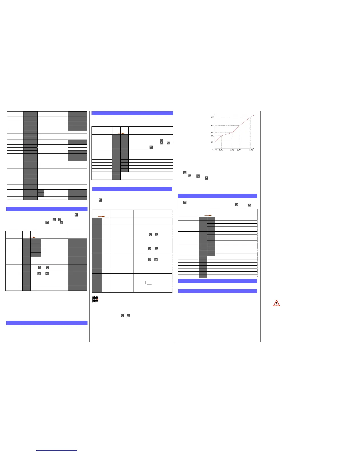
Multi-Point Scaling
When enabled (
Mm =
), up to 9 breakpoints can
be set to compensate for non-
linear input signals.
For each breakpoint, the input
scale value (n) is
entered in % of input span,
followed by the value to be
shown (n) in display
units.
Each breakpoint’s input scale
value must be higher than the
previous value, but the display
values can be higher or lower.
Any scale value set to 100%
becomes the last in the series.
Tare Feature
When Tare is enabled ( = ), it can be used to set the displayed value to zero
automatically, by making the PV Offset parameter equal, but opposite to, the current
process variable value. Tare can be initiated via the Digital Input (if fitted), with a
communications command via the RS485 module (if fitted) or by using the following key
press sequence:
Press until the process variable is displayed.
Hold down and together for three seconds until the display shows
?
Release both keys and press within 3 seconds to confirm the request.
The display should read briefly, then begin responding to input signal changes. This
will have no effect on any stored Max or Min values until they are reset. Once Reset the
Max and Min value will follow the displayed value that has gone through the tare
process
Note: Tare request is aborted if this sequence is not followed exactly.
9. PRODUCT INFORMATION MODE
First select Product information mode from Select mode (refer to section 2).
Press to view each parameter (while this key is pressed, and for 1 sec after, the
parameter legend is shown, followed by its value). Hold down and press to
return to Select mode. Note: These parameters are all read only.
Parameter
Legend
for 1 sec
followed
by
Value Description
Input type
Universal input
Option 1 module type
fitted
No option fitted
Relay output
Enhanced Resolution Linear DC
Voltage/Current Output
Option 2 module type
fitted
No option fitted
Relay output
Dual Relay (outputs 2 & 4)
Linear DC voltage / current output
Option 3 module type
fitted
No option fitted
Relay output
Auxiliary Option A
module type fitted
No option fitted
RS485 communications
Firmware type
Value displayed is firmware type number
Firmware issue
Value displayed is firmware issue number
Product Rev Level
Value displayed is Product Revision Level
Manufactured Date
Mm
Month & year of manufacture. Format mmyy
Serial number 1
First four digits of serial number
Serial number 2
Middle four digits of serial number
Serial number 3
Last four digits of serial number
10. SERIAL COMMUNICATIONS
Refer to the full user guide (available from your supplier) for details.
11. SPECIFICATIONS
UNIVERSAL INPUT
Strain Gauge:
).
Isolation: Isolated from all outputs.
Dynisco
38 Forge Parkway
Franklin Mass. 02803
: Universal input must not be connected to operator
accessible circuits if single relay outputs are connected to a
hazardous voltage source. Supplementary insulation or
input grounding would then be required
Sensor Break Detection
. Strain Gauge: Depending on User setting can cause
input to fail high scale or low scale reading .Reading will fail
on either, Sig+ or Sig- loss, or incorrect excitation output
<0.8mA and >33mA supply.
Thermocouple, RTD, 4 to 20 mA, 2 to 10V and 1 to 5V
ranges only. High alarms activate for thermocouple/RTD
sensor break, low alarms activate for mA/V DC sensor
break.
LOGIC INPUT
Voltage Input:
Reset or Tare occurs on high (3 to 5VDC) to low <0.8VDC,
or Open to Closed transition.
Isolation: No isolation from inputs and other outputs.
OUTPUTS
Relay
Contact Type & Rating: Single pole double throw (SPDT), latching or non-latching
action (selectable); 2A resistive at 120/240VAC.
Lifetime: >500,000 operations at rated voltage/current.
Isolation: Basic Isolation from universal input.
Dual Relay
Contact Type & Rating: Single pole single throw (SPST), latching or non-latching
action (selectable); 2A resistive at 120/240VAC.
Lifetime: >200,000 operations at rated voltage/current.
Isolation: Reinforced safety isolation from inputs and other outputs.
Linear DC
Accuracy:
0.1% of span (mA @ 250Ω, V @ 2kΩ).
Resolution: 15 3/4 bit (1 part in 52K) and updated at about 65ms
intervals. (130ms settling time)
Isolation: Reinforced safety isolation from inputs and other outputs.
Transmitter PSU
Power Rating: 24V TxPSU Module; Unregulated 20 to 28V DC into 910
min
Linear output Module; Regulated 0.0 to 10.0V into 500
min.
Isolation: Reinforced safety isolation from inputs and other outputs.
SERIAL COMMUNICATIONS
Physical: RS485, at 1200, 2400, 4800, 9600 or 19200 bps.
Protocols: Selectable between Modbus and West ASCII.
Isolation: Reinforced safety isolation from all inputs and outputs.
OPERATING CONDITIONS (FOR INDOOR USE)
Ambient Temperature: 0°C to 55°C (Operating), –20°C to 80°C (Storage).
Relative Humidity: 20% to 95% non-condensing.
Supply Voltage and
Power:
100 to 240VAC
 Loading...

