Do you have a question about the Dynon Avionics SkyView HDX Series and is the answer not in the manual?
Describes the manual's organization: Airworthiness Limitations, System Description, Troubleshooting, Removal/Installation, Service.
Overview of SkyView HDX system functions, listing Required and Optional functions.
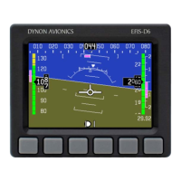
Describes the EFIS-D10A's role as a backup Altitude, Attitude, and Airspeed indicator.
Details the multi-functional, high-definition LCD displays, their sizes, and features.
Explains how SkyView HDX displays present Primary and Optional Content in various layouts.
Details the functions and operation of the buttons and knobs on the SkyView HDX display.
Explains how to access and use the Function Control Menu (MENU) for system functions.
Describes Setup Menu and In-Flight Setup Menu for configuration and calibration.
Details the Primary Flight Display (PFD) layout, content, and configuration options.
Explains the Attitude Indicator function, its sub-indicators, symbols, and reference scales.
Describes the Altitude Indicator, its tape-style display, and how to set altitude and baro pressure.
Details the Airspeed Indicator, its tape-style display, and how to set airspeed bugs.
Explains the Vertical Airspeed Indicator, its tape-style display, and setting vertical speed bugs.
Describes the HSI, its compass-style display, and its sub-indicators and reference scales.
Details the Wind Indicator location and data sources used for its display.
Explains the Navigation Source Indicator and how to toggle between NAV sources.
Describes the OAT Indicator location and data sources used for its display.
Covers Clock, G-Meter, Traffic Indicators, and Angle of Attack functions.
Details the synthetic vision representation of terrain and obstacles for advisory purposes.
Explains Moving Map and VFR GPS Navigator functions using navigation databases and GPS data.
Details updating navigation databases and charts for the SkyView HDX system.
Explains the need for valid GPS sources for Moving Map and Navigation functions.
Describes how SkyView HDX uses ADS-B IN Receiver data for weather and traffic indicators.
Details the Message Notification Area, and the three categories of alerts: messages, cautions, warnings.
Describes the EFIS-D10A as a standby display providing attitude, airspeed, and altimeter.
Details the SV-BAT-320 backup battery's function, power provision, and charging.
Explains the ADAHRS module, its sensors, and how it generates PFD functions.
Describes the SV-MAG-236 remote magnetometer for locating areas free of magnetic disturbances.
Details the OAT sensor, its external mounting, and connection options.
Describes the SV-GPS-2020 for high-integrity GPS data, required for ADS-B Out mandate.
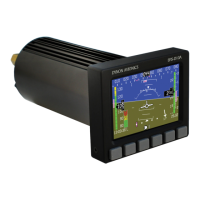
Details the SV-XPNDR-261, a TSO remote-mounted Mode-S transponder for TIS-B and ADS-B Out.
Explains the SV-ADSB-472 dual band ADS-B IN receiver for weather and traffic data.
Details the SV-EMS-220 for engine gauges, measuring various engine and environmental parameters.
Describes display options for engine monitoring information on single-engine aircraft.
Explains display requirements for engine monitoring information on twin-engine aircraft.
Details the SV-COM-X25/X83 VHF COM Radio, its control panel, and transceiver.
Describes the SV-ARINC-429 module for connecting advanced third-party GPS Navigators.
Details the optional SV-KNOB-PANEL for dedicated knobs for ALT, BARO, and HDG/TRK bugs.
Explains the optional, digitally controlled Autopilot System for flight path control.
Details how to engage Autopilot servos using the Control Page or Control Panel.
Describes how to engage the Yaw Damper independently from the Autopilot.
Details the SV-AP-PANEL, an optional control panel for Autopilot functions and modes.
Describes the SV-BUTTON-APDISC, the required Autopilot Disconnect button.
Details the SV-BUTTON-LEVEL, an optional button to activate/deactivate Level Mode.
Describes the SV-NET-HUB accessory for simplifying SkyView HDX Network component connections.
Details the Panel Mount USB Port for extending access to USB ports for file transfers.
Explains how SkyView HDX indicates failures with Red X, and how sensor failures are displayed.
Provides troubleshooting steps for blank screens on SkyView HDX displays.
Lists and describes fault messages like CPU TEMP CRITICAL and TOUCH PANEL FAULT.
Troubleshooting steps for when audio messages are not heard from the system.
Troubleshooting the ADAHRS module, including Red X, airspeed, and altitude issues.
Addresses Red X on PFD, indicating ADAHRS module communication failure.
Troubleshooting airspeed issues due to pitot sensor or line obstruction/leak.
Troubleshooting frozen altitude indication due to static sensor or tube obstruction.
Troubleshooting incorrect Density Altitude or OAT indications, possibly due to OAT sensor.
Troubleshooting missing AoA audio alerts: tubing, blockage, connector issues.
Troubleshooting HDG SOURCE FAIL message related to the Remote Magnetometer.
Troubleshooting GPS issues: Red X over Moving Map, incorrect GPS position.
Troubleshooting backup battery messages: B/U BATT TEST NEEDED, B/U BATT UNAVAIL.
Troubleshooting EFIS-D10A warnings: Internal error, unstable temp, low battery.
Troubleshooting EMS module: Red X, sensor failures, wiring faults.
Troubleshooting transponder warnings: Antenna fault, no ADS-B position, heat, power issues.
Troubleshooting ADS-B IN receiver: No traffic/weather, status messages.
Troubleshooting COM system: Panel not illuminated, communication messages.
Troubleshooting ARINC 429 module: No GPS/NAV data, communication issues.
Troubleshooting missing AoA audio alerts: tubing, blockage, connector issues.
Troubleshooting Autopilot system: Servos offline messages.
Addresses servos offline messages, checking power, breakers, and connectors.
Troubleshooting servo slip messages, checking shear screw failure.
Troubleshooting AP control panel: buttons not working, LED status.
Troubleshooting LEVEL button: error messages, wiring, or button replacement.
Troubleshooting Autopilot Disconnect button: AP BROKEN/STUCK messages, wiring.
Troubleshooting Knob Control Panel: knobs not controlling functions, LED status.
Troubleshooting Panel Mount USB Port: ports not working, cable connection.
References the installation record document for component locations and notes.
Guides on accessing system components, typically located behind the instrument panel.
Lists mounting hardware required for SkyView HDX system components.
Provides removal and installation procedures for the primary and secondary SkyView HDX Displays.
Specifies typical locations for primary (left) and secondary (right) displays.
Step-by-step instructions for removing the SkyView HDX Display unit.
Step-by-step instructions for installing the SkyView HDX Display unit.
Provides removal and installation procedures for the ADAHRS module.
Specifies the typical mounting location of the ADAHRS module behind the display.
Step-by-step instructions for removing the SV-ADAHRS-200 ADAHRS module.
Step-by-step instructions for installing the SV-ADAHRS-200 ADAHRS module.
Provides removal and installation procedures for the Outside Air Temperature (OAT) sensor.
Specifies the typical location of the OAT sensor under the left wing.
Step-by-step instructions for removing the SV-OAT-340 OAT sensor.
Step-by-step instructions for installing the SV-OAT-340 OAT sensor.
Provides removal and installation procedures for the Remote Magnetometer unit.
Specifies the location of the Remote Magnetometer unit as per installation record.
Step-by-step instructions for removing the SV-MAG-236 Remote Magnetometer.
Step-by-step instructions for installing the SV-MAG-236 Remote Magnetometer.
Provides removal and installation procedures for the GPS Antenna/Receiver.
Specifies the typical location of the GPS Antenna/Receiver on the airplane's top surface.
Step-by-step instructions for removing the SV-GPS-2020 GPS Antenna/Receiver.
Step-by-step instructions for installing the SV-GPS-2020 GPS Antenna/Receiver.
Provides removal and installation procedures for the Backup Battery unit.
Specifies the typical mounting location of the Backup Battery on the avionics tray.
Step-by-step instructions for removing the SV-BAT-320 Backup Battery.
Step-by-step instructions for installing the SV-BAT-320 Backup Battery.
Provides removal and installation procedures for the EFIS-D10A Standby Display.
Specifies the typical location of the EFIS-D10A on the left instrument panel.
Step-by-step instructions for removing the EFIS-D10A Standby Display.
Step-by-step instructions for installing the EFIS-D10A Standby Display.
Provides removal and installation procedures for the EFIS-D10A Backup Battery.
States the EFIS-D10A Backup Battery is internal to the unit.
Step-by-step instructions for removing the EFIS-D10A Backup Battery.
Step-by-step instructions for installing the EFIS-D10A Backup Battery.
Provides removal and installation procedures for the Engine Monitoring System module.
Specifies typical locations for the EMS module in single and twin-engine aircraft.
Step-by-step instructions for removing the SV-EMS-220 EMS module.
Step-by-step instructions for installing the SV-EMS-220 EMS module.
Details removal and installation of the oil pressure sensor, referring to aircraft manuals.
Details removal and installation of the oil temperature sensor, referring to aircraft manuals.
Details fuel pressure sensor location and removal/installation, referring to aircraft manuals.
Details fuel flow sensor location and removal/installation, referring to aircraft manuals.
Details fuel level sensor location and removal/installation, referring to aircraft manuals.
Details carburetor temp sensor location and removal/installation, referring to aircraft manuals.
Details CHT sensor location and removal/installation, referring to aircraft manuals.
Details EGT sensor location and removal/installation, referring to aircraft manuals.
Details TIT sensor location and removal/installation, referring to aircraft manuals.
Details Amp sensor location and removal/installation, referring to aircraft manuals.
Explains the voltmeter sensor connection to the EMS module for voltage indication.
Details tachometer sensor connection to magneto control switch for pulse signals.
Details MAP sensor location and removal/installation, referring to aircraft manuals.
Details flap position sensor location and removal/installation, referring to aircraft manuals.
Details landing gear position sensor location and removal/installation, referring to aircraft manuals.
Provides removal and installation procedures for the Transponder module.
Specifies transponder location as close to its antenna as possible.
Step-by-step instructions for removing the SV-XPNDR-261 Transponder.
Step-by-step instructions for installing the SV-XPNDR-261 Transponder.
Provides removal and installation procedures for the ADS-B IN Receiver.
Specifies the typical location of the ADS-B IN Receiver behind the SkyView HDX Display.
Step-by-step instructions for removing the SV-ADSB-472 ADS-B IN Receiver.
Step-by-step instructions for installing the SV-ADSB-472 ADS-B IN Receiver.
Provides removal and installation procedures for the ADS-B Antenna.
Specifies the typical location of the ADS-B Antenna on the underside of the airplane.
Step-by-step instructions for removing the ADS-B Antenna.
Step-by-step instructions for installing the ADS-B Antenna.
Provides removal and installation procedures for the COM Transceiver.
Specifies the location of the COM Transceiver as per installation record.
Step-by-step instructions for removing the SV-COM-T25/T8 COM Radio Transceiver.
Step-by-step instructions for installing the SV-COM-T25/T8 COM Radio Transceiver.
Provides removal and installation procedures for the COM Control Panel.
Specifies the typical location of the COM Control Panel on the left instrument panel.
Step-by-step instructions for removing the SV-COM-PANEL COM Radio Control Panel.
Step-by-step instructions for installing the SV-COM-PANEL COM Radio Control Panel.
Provides removal and installation procedures for the ARINC 429 Connection Module.
Specifies the typical location of the ARINC 429 Connection Module behind the display.
Step-by-step instructions for removing the ARINC 429 Connection Module.
Step-by-step instructions for installing the ARINC 429 Connection Module.
Provides removal and installation procedures for the Angle of Attack (AoA) probe.
Specifies the typical location of the AoA probe underneath the left or right wing.
Step-by-step instructions for removing the AoA Probe.
Step-by-step instructions for installing the AoA Probe.
States autopilot servo installation is specific to airplane model.
References installation record for specific autopilot servo locations.
References Autopilot Servo Installation Manual for servo removal.
References Autopilot Servo Installation Manual for servo installation.
Provides removal and installation procedures for the Autopilot Control Panel.
Specifies typical location of Autopilot Control Panel on left instrument panel.
Step-by-step instructions for removing the SV-AP-PANEL Autopilot Control Panel.
Step-by-step instructions for installing the SV-AP-PANEL Autopilot Control Panel.
Provides removal and installation procedures for the Autopilot Level Button.
Specifies typical location of the LEVEL button on the left instrument panel.
Step-by-step instructions for removing the SV-BUTTON-LEVEL Autopilot Level Button.
Step-by-step instructions for installing the SV-BUTTON-LEVEL Autopilot Level Button.
Provides removal and installation procedures for the Autopilot Disconnect Button.
Specifies typical location of the A/P DISC button on the left instrument panel.
Step-by-step instructions for removing the SV-BUTTON-APDISC Autopilot Disconnect Button.
Step-by-step instructions for installing the SV-BUTTON-APDISC Autopilot Disconnect Button.
Provides removal and installation procedures for the Yoke-Mount Autopilot Disconnect Button.
Specifies the pilot's control yoke as the location for the Autopilot Disconnect Button.
Step-by-step instructions for removing the Yoke-Mount Autopilot Disconnect Button.
Step-by-step instructions for installing the Yoke-Mount Autopilot Disconnect Button.
Provides removal and installation procedures for the Knob Control Panel.
Specifies typical location of Knob Control Panel on left instrument panel.
Step-by-step instructions for removing the SV-KNOB-PANEL Knob Control Panel.
Step-by-step instructions for installing the SV-KNOB-PANEL Knob Control Panel.
Provides removal and installation procedures for the Panel Mount USB Port.
Specifies typical location of Panel Mount USB Port under the SkyView HDX Display.
Step-by-step instructions for removing the Panel Mount USB Port.
Step-by-step instructions for installing the Panel Mount USB Port.
Outlines periodic maintenance tasks including component checks and display cleaning.
Provides instructions for downloading and updating the SkyView HDX system software.
Instructions for downloading and loading aviation databases and charts onto the display.
Details how to perform the mandatory 12-month backup battery test for SkyView HDX.
Explains the procedure for testing the EFIS-D10A internal backup battery capacity.
Procedures for performing pitot and static system leak tests.
Calibration steps for IAS and AoA pressures in a windless environment.
In-flight calibration procedure for the Angle of Attack sensor.
Tests required for transponder installation verification per FAR and AC standards.
Procedure for manually switching the transponder between ALT and GND modes.
Procedures for on-ground and in-flight compass calibration for heading accuracy.
Step-by-step guide for performing on-ground compass calibration.
Guidance for performing optional in-flight compass calibration for improved accuracy.
| Brand | Dynon Avionics |
|---|---|
| Model | SkyView HDX Series |
| Category | Avionics Display |
| Language | English |