REV E, ECN 13281 02/28/2017
2
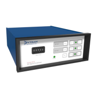
OPERATING INSTRUCTIONS MODEL 4010 3-CHANNEL DC SIGNAL CONDITIONER AMPLIFIER
INTRODUCTION
Model 4010 is a microprocessor-controlled, 3-
Channel DC Signal Conditioner Amplifier designed to be
used with bridge type or differential output accelerometers
and pressure transducers. Model 4010 incorporates variable
gain adjustment, shunt calibration capability, and multiple
excitation level settings. For various applications where
specific frequency roll-off is required, Model 4010 has a
variety of optional 2-pole high and low pass filter modules
available for purchase under Series 4198A. See Table 1:
Optional Filters for corner frequency options. Dytran
Instruments new 3-Channel DC Signal Conditioner offers a
multitude of features in a simple bench top enclosure for
ease of use.
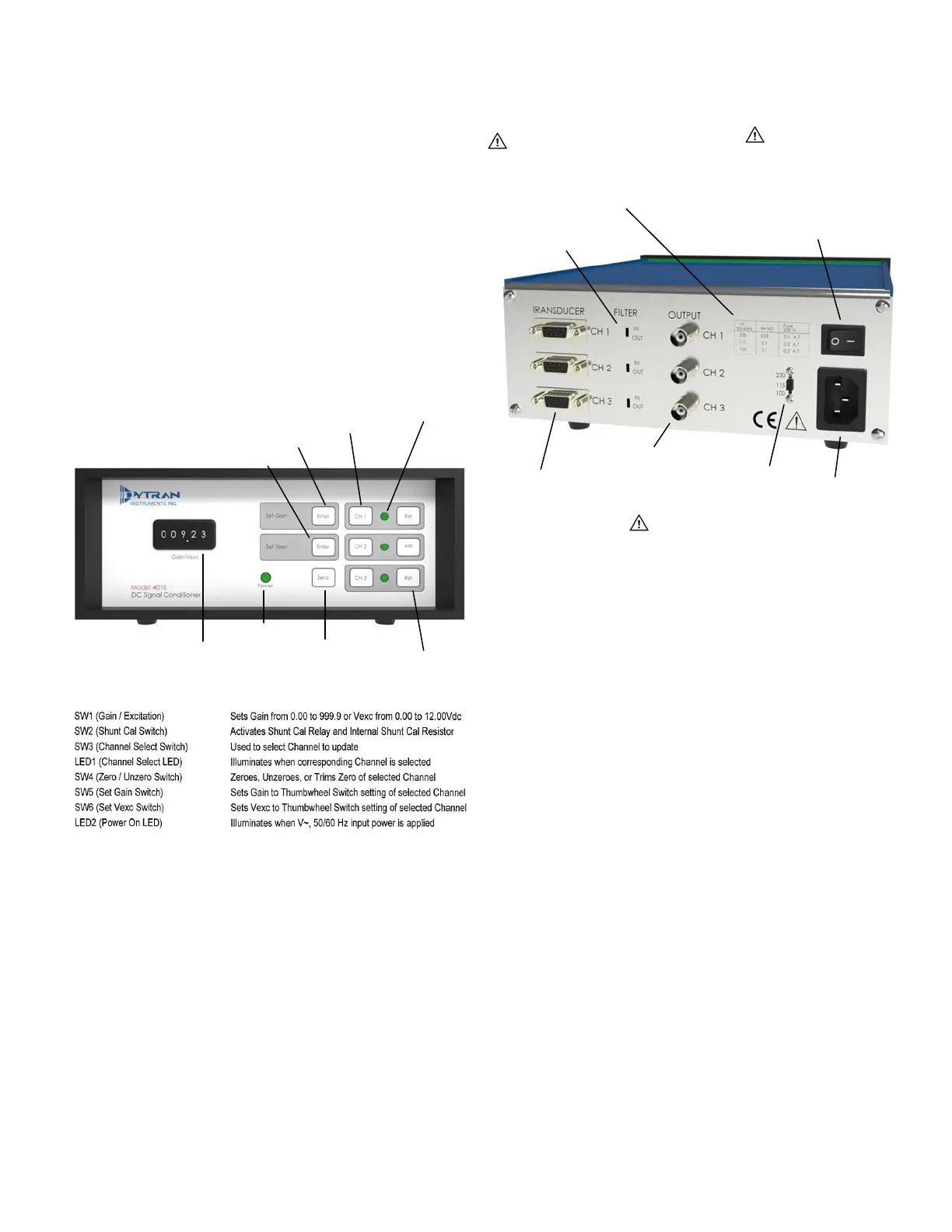
FRONT PANEL
REAR PANEL
DESCRIPTION
Model 4010 utilizes a microprocessor SLEEP mode
to eliminate high frequency clock noise and their
associated harmonics. The microprocessor WAKES
momentarily to acknowledge front panel switch depressions
then goes to SLEEP immediately after processing and
executing the requested function. This allows the amplifiers
to operate with minimum self generated noise and provides
clean, clock free amplified signals.
The Model 4010 uses dual 12-bit DAC's, for each
channel, to autozero the input and output amplifiers for DC
input signals. Input signals with magnitudes of +/-10 Vdc can
be zeroed. Unzeroing the amplifier zeroes both autozero
DAC's. A unique output DAC trimming routine, allows
trimming the output zero to within +/-1 mVdc. Dual 12-bit
DAC's, for each channel, are also used to set amplifier gains
from 0.00 to 999.9 with +/-0.5% precision. Amplifier gains
can be changed "on the fly" without damage to the
instrument.
Each of the 3 amplifiers has a 150 kHz full power
and a 200 kHz small signal bandwidth and can drive 10mA
into a 1 K ohm load. A filter socket is provided, for each
amplifier, to filter broadband noise. A variety of optional 2-
pole high and low pass filter modules are available for
purchase under series 4198A and can be installed in these
sockets. See Table 1: Optional Filters for corner frequency
options.
Set Vexc Switch (SW6)
Set Gain Switch (SW5)
Channel Select Switch (SW3)
Channel Select LED
Thumbwheel Switch
Setting Gain or Vexc (SW1)
Power On LED
Zero/Unzero Switch
SW4
Shunt Cal Switch
SW2
Filter In/Out Switch
CAUTION Verify fuse with proper V~
and current is installed in fuseholder
prior to applying AC Input Power.
Voltage/Rated Current/
Fuse Rating Chart
CAUTION Verify fuse with
proper V~ and current is
installed in fuseholder and
Voltage Selector switch is
properly set before turning
on Power On/Off Switch.
Power On/Off Switch
Transducer Connector
Out
ut BNC Connector
Voltage Selector Switch
AC Power Input
CAUTION Select Proper AC Input Voltage
before applying AC Input Power
 Loading...