REV E, ECN 13281 02/28/2017
4
Unzeroing the desired channel.
Note: Unzeroing the desired channel sets both autozero
DAC's to zero. This sets the amplifier to its natural zero
position. The output of the amplifier is offset by its own offset
voltage.
Step 1: Unzero the amplifier
a) Depress the Channel Select Switch for CH1, CH2
or CH3. The appropriate Channel Select LED will
illuminate and stay illuminated.
b) Depress and hold the ZERO Switch (SW4)
until the appropriate Channel Select LED
extinguishes. The selected Channel amplifier
is unzeroed.
Applying an internal shunt calibration resistor (Rsh) to
the selected channel bridge network.
Note: Internal solder jumpers allow for a positive or negative
responding Rsh. The shunt cal resistors are removable and
may be installed by the user. Reference Location of Filter
Modules and Rsh Resistor in the figure below
WARNING: Turn Input Power Switch OFF before removing
power cable from the instrument. Remove power cable from
the instrument before disassembling any part of the
instrument.
a) Simply depress and hold the Rsh Switch for
the desired channel amplifier. The shunt cal
resistor is applied to the appropriate
transducer bridge circuit terminals for the duration
that the Rsh Switch is depressed.
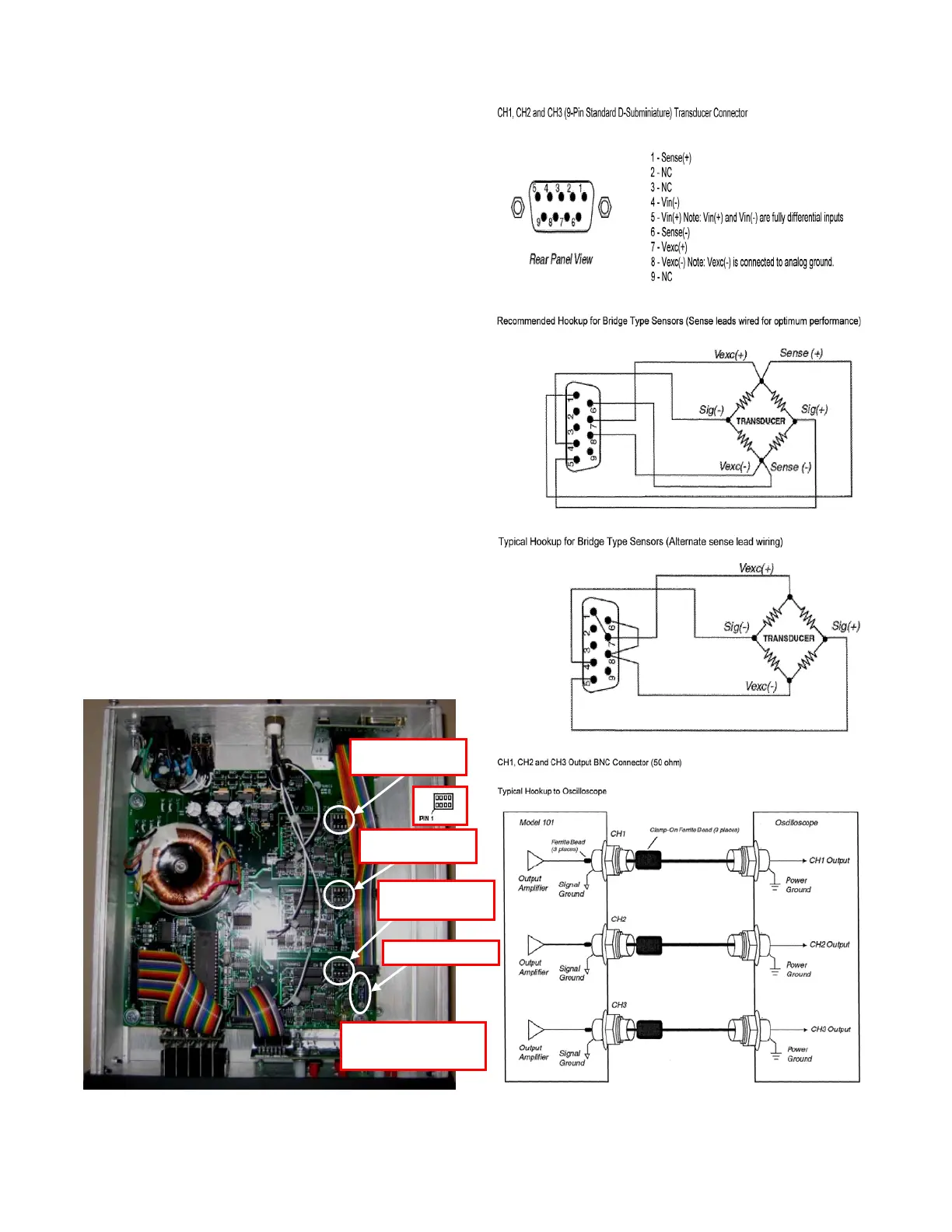
Figure 1: Location of optional filter modules and Rsh Resistors.
WIRING INFORMATION
Filter Module Socket
for CH3
Filter Module Socket
for CH2
Rsh resistor for CH1
Filter Module Socket
for CH1
Note: Rsh resistor for CH2 and
CH3 are in similar location for
corresponding channel