www.e-t-a.de
REX12-Tx-E electronic circuit protector
2045
7
4
REX12-Tx-E electronic circuit protector
Description – EM12-T-E supply module
Operating voltage U
B
DC 24 V (18 ... 30 )
Operating voltage I
B
max. 40 A
Reverse polarity protection Yes
Signalling EM12-T01-001-DC24V-40A-E
Closed current I
0
typical 10 mA
Potential-free max. DC 30 V/0.5 A
Si auxiliary contact min. 10 V/1 mA
Si group signalisation auxiliary contact, closing contact
Terminal: Si (13) / Si (14)
Normal condition: Auxiliary contact closed
based on all protection modules
- when ON, continuous load output
- when OFF, load output off
Error condition: Auxiliary contact open
based on one or more protection modules
- after an overload/short circuit
disconnection
- after undervoltage release of operating
voltage in ON condition with autoreset
- with no operating voltage U
B
in the
supply module
Insulation co-ordination 0.5 kV/pollution degree 2
Power failure-
bridging time for Si up to 10 ms
Screw terminals LINE+
Push-in terminal PT 10 0.5 mm
2
to 10 mm
2
, flexible
AWG20 – AWG8 str.
Stripping length 18 mm
Screw terminals 0 V / Si 13 / Si 14
Push-in terminal PT2.5 0.14 mm
2
to 2.5 mm
2
, flexible
AWG24 – AWG14 str.
Stripping length 8 mm to 10 mm
Dimensions (w x h x d) 12.5 x 80 x 98 mm
Mass approx. 52 g
Circuit protectors can be mounted side-by-side
REX12-Tx1-x-E or
REX12-TA2-x-E or
REX12D-TE2-E 2-channel max. 16 pieces
The EM12-T-E supply module receives the DC 24 V supply voltage,
e.g. from a timed switched mode power supply, and distributes it to
the installed circuit protectors via the integral connector arm of the
REX12-T-E.
The potential-free Si auxiliary contact in the EM12-T-E indicates any
detected failures through the circuit protector, e.g. to the superordinate
control unit (CPU).
Technical data (T
U
= +23 °C, U
B
= DC 24 V)
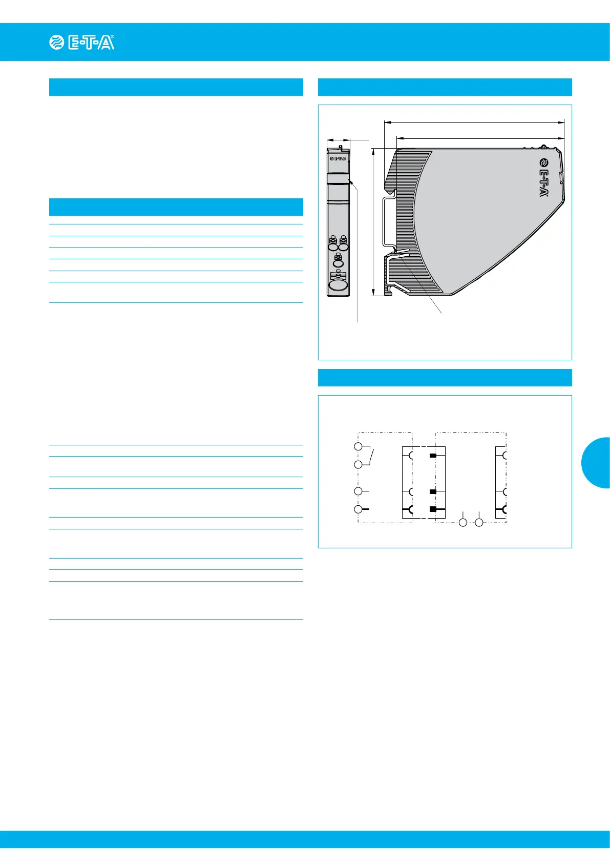
Dimensional drawing EM12-T01-xxx-E supply module
98
38.6
91.5
36.0
snap-on socket for
rail EN 60715-35x7.5
Label e.g. from
Phoenix Contact ZBF-12
80
12.4
4.89
EM12-
T01-001
DC24V
40 A
13 14
OV
LINE +1
GERMANY
Schematic diagram EM12-Txx-xxx-E with REX12-xx-E
EM12-T01-001-DC24V-40A-E
LOAD+ 2.1 | (2.2)
LINE+1
EM12-T
max. 16 pcs
REX12-T
0 V
13
14
 Loading...