© EA Elektro-Automatik, DE-41747 Viersen, Helmholtzstr. 31-33, Tel. 02162-3785-0, Fax. 02162-16230
11
1. Introduction
The optional Ethernet interface provides a network connection in form of a standard RJ45 Ethernet port, plus a stan-
dard RS232 port. They can only be used alternatively, whereas the data transmission speed of the RS232 is much
slower compared to the Ethernet port, because the RS232 is working at 9600 baud. Time-critical measurements are
thus only advised to be performed using the Ethernet port. The Ethernet option offers a set of features which are,
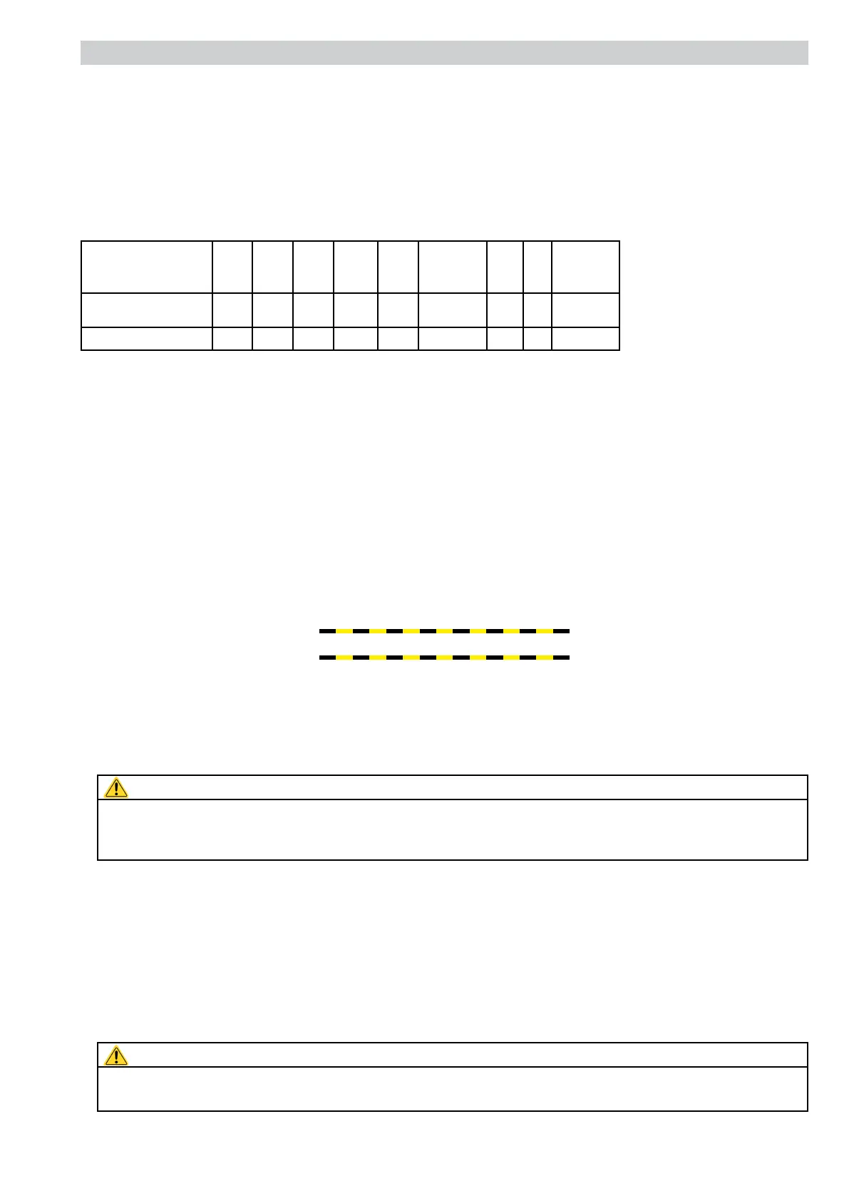
caused by the different designs of our PS series, not identical with every model. The table gives an overview, which
series can provide which functionality in combination with the Ethernet interface.
PSseries Uset Iset Pset Umon Imon CC/CV/CP OVP OT
Output
on/off
PS9000Mod.2004
1,5...9kW
x x x x x x x x
HV9000
x x x x x
(1
x
x = feature present
(1 = only CC/CV
Meaning of the abbreviations:
Uset - Set the set value for voltage
Iset - Set the set value for current
Umon - Read out (=measure) the actual voltage
Imon - Read out (=measure) the actual current
CC/CV/CP - Operation mode CC (Constant Current) or CV (Constant Voltage), as well as CP (Constant Power)
Note: these modes exclude each other, that means only one can be active
A logical 1 (=high) means that it is active (in combined modes a 1 means CC active and a 0 that CV is active)
OVP - Query alarms, in this case overvoltage protection (is logical 1, as long as OVP is present)
OT - Query alarms, in this case overtemperature protection (is logical 1, as long as OT is present)
1.1Basicitemstoknowforoperation
Important!Readthisbeforerstuse!
• When sending a command the rst time after the device has been powered, the power supply will automatically
switch to external control and the set values for current and voltage are set to zero.
• Current and voltage have to be set both during remote control. It means, you can’t set voltage externally via the
Ethernet interface and current on the front of the device with the potentiometer, for example.
• Activating the „Local“ switch on front panel (where present) interrupts remote control as long as the switch is acti-
vated. The device switches to manual control and it does not reset the interface card.
Attention!
Activatingswitch„Local“whiletheDCoutputisoncanresultinunwantedvoltageleaps,becausethe
deviceswitchestomanualcontrolandthusthevoltage/currentsettingsfromthepotentiometersonthe
frontbecomeinstantlyeffective.
• The Output On/Off switch for the DC power output can not be overridden by the command OUTP, that means if the
switch is pressed, i.e. output = off, and external control is active, the unit will not put out voltage (does not apply to
PS 9000 models from 2004 or later).
• Models with power adjustment, like a PS 9000 from 2004 or later, denitely require a power set value which is not
provided by the interface. It it thus required to dene the power set value via the analogue interface on the rear,
either by a potentiometer resp. external voltage (pin 1, with reference to pin 14) or by a bridge between pin 1 and
pin 18 (which will dene the power to 100%).
• All SCPI commands can also be set via the RS232 port. In order to use the RS232 for remote control, the IP
programming procedure has to be canceled by denying the question „Program IP address?“. After this, all SCPI
commands can be used as normal via RS232.
Attention!
TheRS232portisnotgalvanicallyisolatedtothePC!Beforeconnectingthisport,eitherforIPprogram-
mingornormalremotecontrol,makesurethatthePCandthepowersupplyareonthesamepotential.
Description