ILER-20 MK2 SSB QRP Transceiver Kit Page 17
Pin "headers"
Place and solder the pins in Mic(3), 12V(2), ATT(2), P1-RXG(3), ANT(2), ALT(2), D7(2), VXO(2),
BFO(2), J1( 3), J2(2), K1(1), K2(1), and S(2).
Place “jumpers” between pins “J2” and “J1-B” and bet ween the active pins of “P1-RXG” (if RX gain
potentiometer is not used).
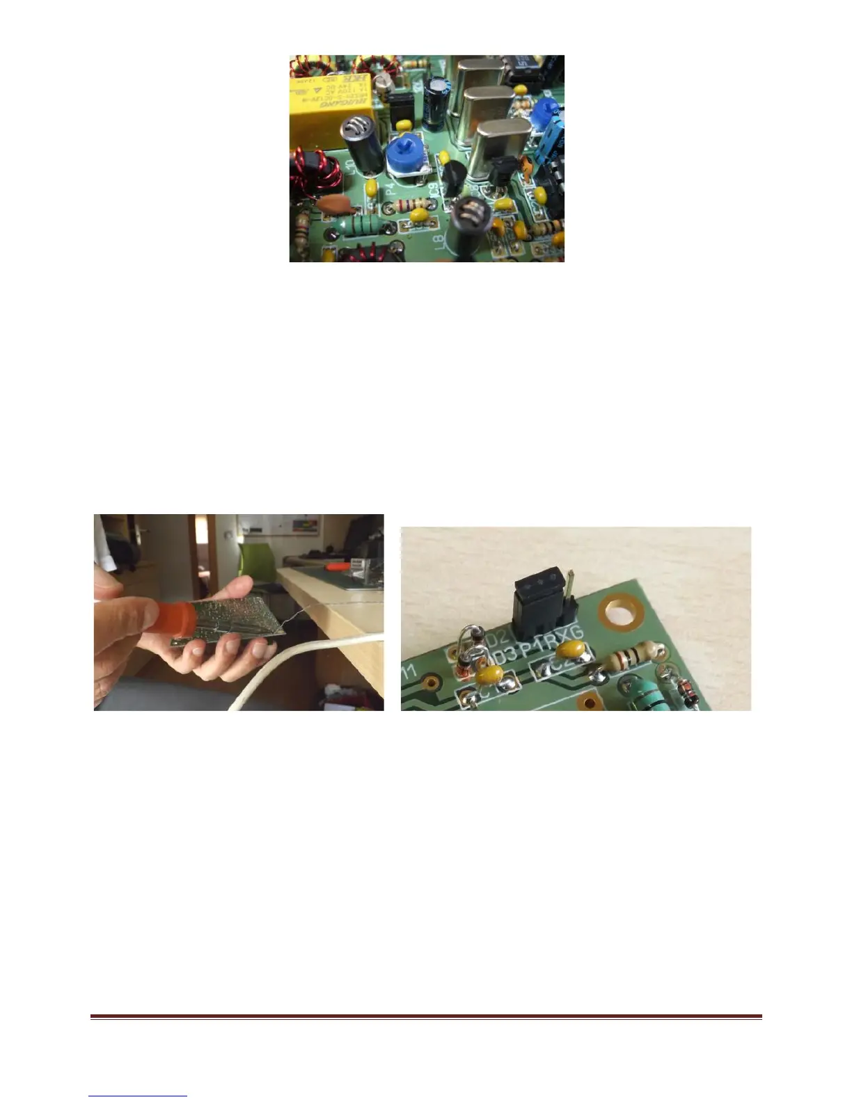
Turn the board over and insert and hold the header in place, using a “jumper” placed on the header while
you solder the pins to avoid burning your fingers. Use your other hand to hold the soldering iron and
move the board t owards the solder to solder the headers in place. If you have someone available to help
you, it will be much easier!
Transistors
All of the transistors have their type printed on t he component body. Place them according to the
corresponding component outline printed on the circuit board. Transistors Q1 through Q11 are all of the
type BC547. Q12 is a 2N2222 and Q13 is a 2N5109; these two transistors have a small tab that must
match up with the component outline printed on t he circuit board. Mount them with 1.5-2mm separation
from the board. Mount the crown-like heatsink, which you will find in the kit's "hardware" bag, onto Q13.
Do not install Q14 (TX power amplifier) yet.
 Loading...