ILER-20 MK2 SSB QRP Transceiver Kit Page 18
Integrated circuits
The component outline for the IC on t he circuit board has a “U” shaped notch on one end, indicating the
end at which pin 1 of the IC is located. There is a similar notch on one end of the sockets. This should be
oriented over the "U" notch outline on the circuit board. Finally, pin 1 of the IC is marked with a small
dimple or dot; this end of the IC should oriented towards the notch in the IC socket or the "U" on the
component outline.
Mount the sockets for IC1, IC2, IC3 and IC4 in the locations printed on the circuit board. Make sure t hat
the sockets lie flat against the circuit board.
Next, insert IC1, IC2, IC3 and IC4 into their respective sockets.
IMPORTANT: Make sure that the IC's are fully inserted into their sockets. A poor cont act between the
socket and IC can cause malfunction of the kit.
Now, mount the voltage regulators IC5, IC6, IC7 and IC8 in their respective locations according to the
markings of the component outline on the circuit board.
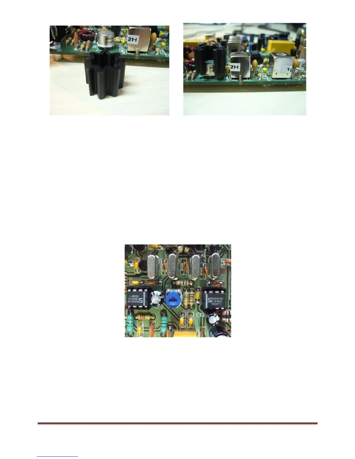
Crystals
Install X1 through X7.
X1, X2, X3 and X4 are part of the SSB filter, and X5 is the oscillator crystal for the BFO. These crystals
have been hand-picked (they have handwritten numbers on them) and have the same resonant
frequency, in order to obtain the best filter quality. The pair X6 & X7 are the VXO crystals.
The crystal housing should not touch the board; place them slightly separated from t he board, at a
distance of 0.5-1mm.