Values are strictly illustrative. T hey will be influenced by the number of turns on L6, the rear fine tuning
trimmer adjustment and the component tolerances.
Upper frequency limit adjus tment.
In the back of the polyvaricon there are two padders (trimmers) for fine adjustment. The lower one is
parallel with CV2 (J1-B) and the top one is parallel with CV3 (J1-A). In the ILER-20 the lower trimmer is
used. This adjustment allows setting the upper frequency limit within a range of more than 10
KHz!
Make t his adjustment with the polyvaricon at its minimum capacitance (completely clockwise).
In the ILER-20 try locating t he padder (trimmer) at its minimum capacitance (completely open) to obtain
the highest possible upper limit.
In the case that, even after spreading the turns to the maximum the range is very large, or compressing
them the range is very s mall, you can take off or add a turn to L6. (one more turn = more range; one less
turn = less range).
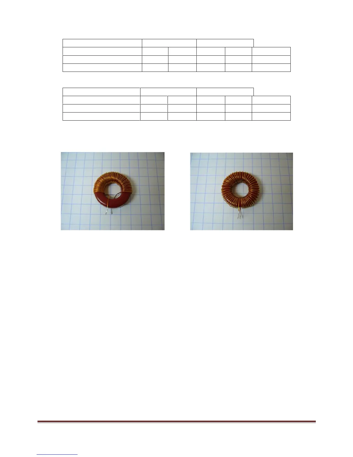
Once you are sure that the VXO range will suit your needs, you will need to secure L6 in position on the
board. I suggest two options:
1) Use a little bit of wax or hot glue (that doesn't contain water) to secure it in the place. Then you m ay
also use a fine layer of nail polish to fix the turns.
Caution: Some glues, due to their composition, may greatly affect the characteristics of L6, even after
curing. You may find that once you have secured inductor L6, the VXO frequency has changed
considerably in relation to the adjustments that were made before. They can also absorb more or less
humidity, affecting the stability.