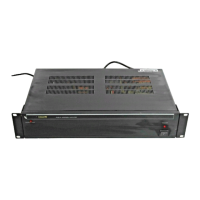
Booster Amplifiers PAB5120E and PAB5240E
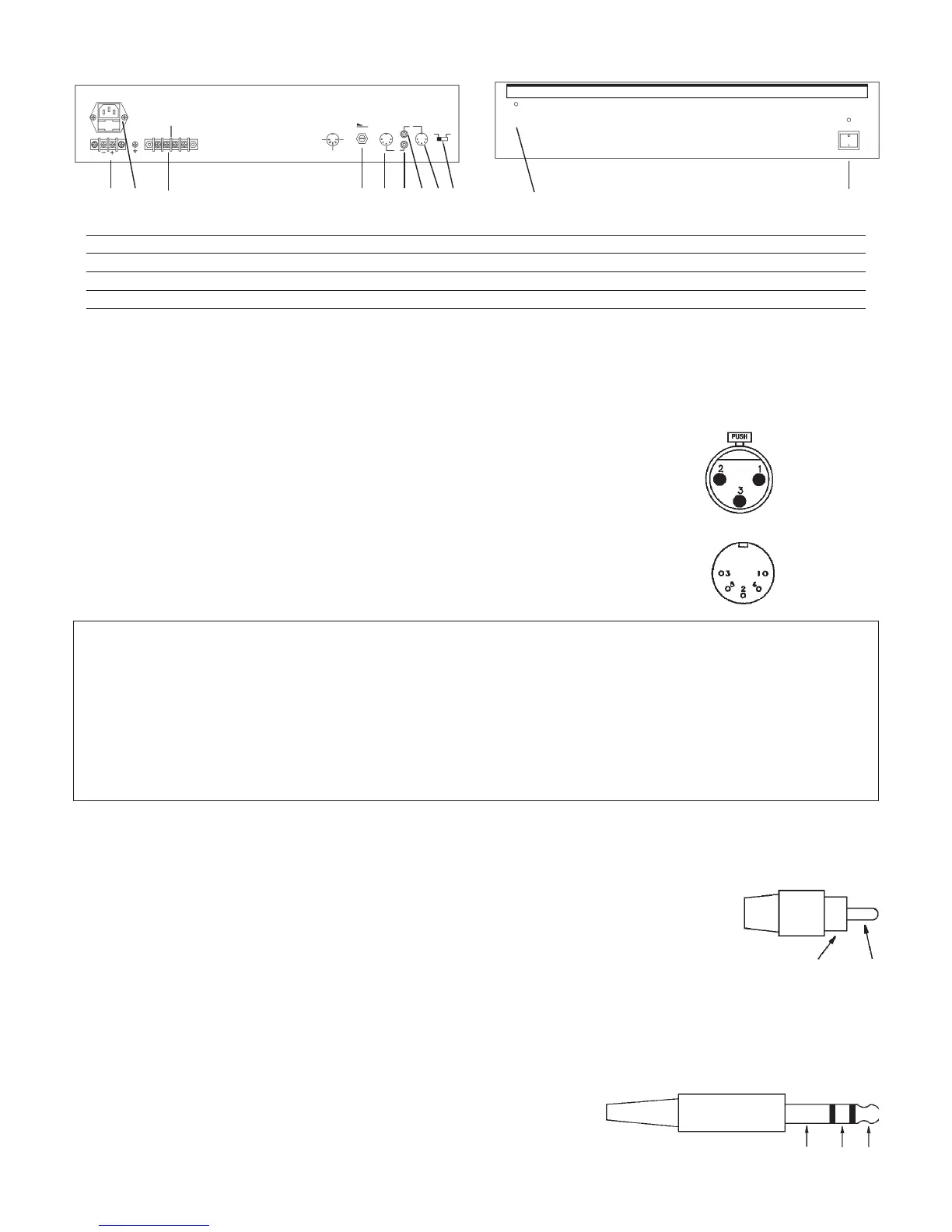
REAR PANEL
OUT
IN
MODEL NO. PA5120E
RATED OUTPUT 120W RMS
MADE IN TAIWAN
MUSIC/SPEECH
220 - 240V~50/60Hz
24V DC
SPEECH ONLY
250V 2.5A
1 4 5 923 6 87
FRONT PANEL
OVERLOAD
10
11
1. Battery Connector 7. Input Socket (Phono)
2. Mains Connector 8. Input Socket (DIN)
3. Loudspeaker Connector 9. Sensitivity Selector
4. Volume Control 10. Input Overload Indicator
5. Output Socket (DIN) 11. Power On/Off Switch
6. Output Socket (Phono)
Mic 1 & Mic 2 Input Connections
These Microphone inputs use an XLR connector for signal input and if required a 180° DIn plug can also be used to obtain priority operation. Ideally a balanced or
floating microphone with an impedance of 600Ω should be used. If priority is required the microphone must also have a normally open volt free switch.
Non Priority Connection (Mixing)
Balanced Operation Unbalanced Operation
Pin 1 Screen Pin 1 Screen
Pin 2 Signal (Live) Pin 2 Signal
Pin 3 Signal (Return) Pin 3 Short to pin 1
Priority Connection
The Signal connections should be made as shown in Non-Priority above.
The 5 pin 180° DIN socket directly above the microphone input socket is used to obtain priority functions
for the input socket. Other features are also available on this socket.
180° DIN SOCKET
Pin Number Function
1 Mute: Used to override Mic inputs 3 to 5 and/or Auxiliary inputs 1 to 3, to override these inputs short to pin 2. This action will
also activate the “Ding Dong” chime.
2 Ground: Connected to the equipment chassis.
3 Busy: Open collector, going to ground when pin 1 is shorted to ground.
4 Speak Now: Open collector, going to ground when pin 1 is shorted to ground and the “Ding Dong” chime has finished.
5 24Vdc Output: Used for phantom powering of other equipment. E.g. Relays, Microphones, etc. Max. current must not exceed
0.5 Amps total (not per socket).
Mic 3 & Aux 1 Connections Microphone 3 is connected exactly the same way as the signal connections for Mic 1 & Mic 2. Please note that no priority
functions are available for this input.
The amplifier leaves the factory pre-configured for this input set as Mic 3, however if needed this can easily be re-configured as an auxiliary input, this is achieved
by the following process:
1. Remove the top case
2. Locate switch on the rear PCB (three switches are located on the rear PCB, the switch required is the left most one when
viewed from the front panel).
3. Set the switch to the position nearest the rear panel.
4. Replace the top cover.
The input Aux 1 uses two standard RCA Phono plugs. These are shorted together internally and provide a mono input.
Pin: Signal
Sleeve: Screen
SLEEVE
PIN
Mic 4, 5 & Aux 2, 3 Connections These inputs are configured at the factory as Auxiliary inputs. The connection for these is exactly the same as for Aux
1 above. These inputs may be re-configured as balanced microphone inputs, this is achieved by the following process:
1. Remove top cover.
2. Locate switch for Mic 4 and/or for Mic 5 (these are located on the PCB along the rear panel, the centre switch is for Mic 4 and the rightmost switch is for Mic
5).
3. Set the switch to the position furthest from the rear panel.
4. Replace the top cover.
The microphone inputs use standard 1/4” Stereo Jack Sockets, these are wired as follows:
Tip: Signal (Live)
Ring: Signal (Return)
Sleeve: Screen
SLEEVE RING
TIP
2
 Loading...