The material contained in this document is the property of Electronics & Innovation Ltd., it is
subject to change without notice.
August 2013 4 Revision B
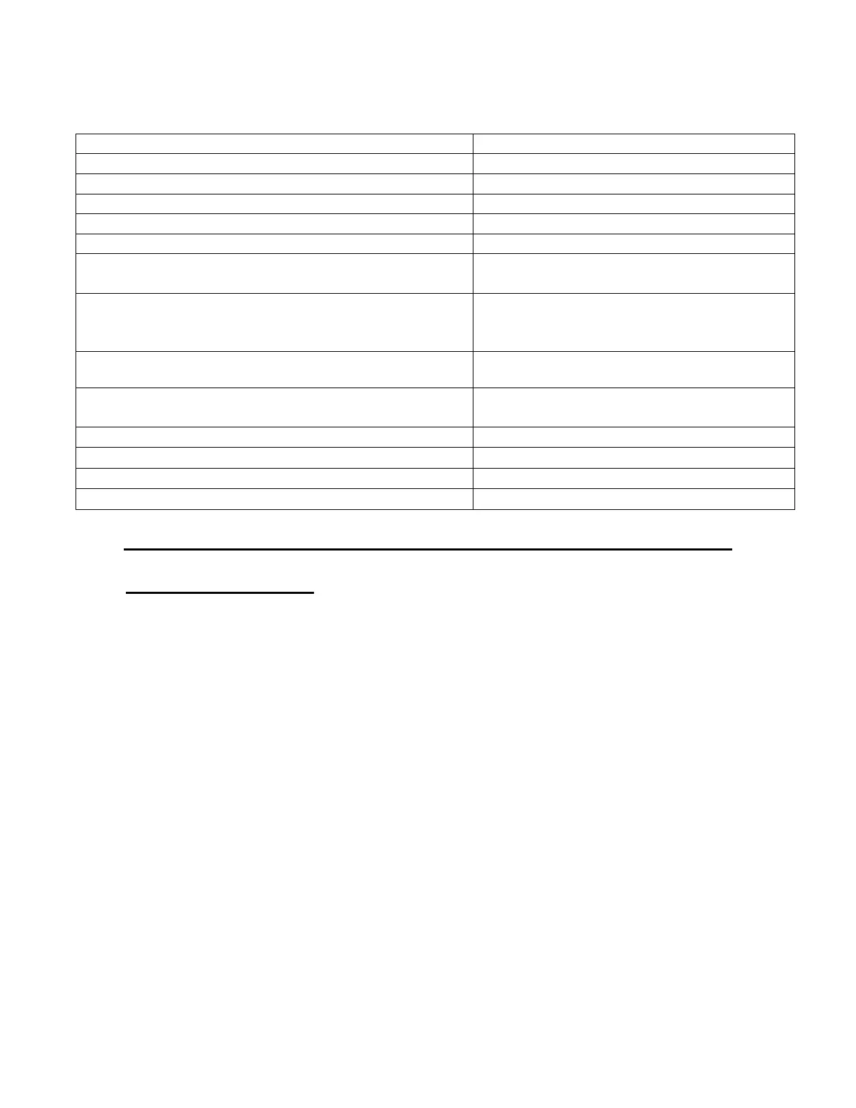
Table 1-1. SPECIFICATIONS
40 dB min, ±1.5 variation.
> -25 dBc at 10 watts output.
50 ohms, VSWR, 1.5:1 Maximum.
50 ohms, VSWR, 2.5:1 Maximum
Continuous operation into any load or
source impedance.
Unit will withstand a + 13dBm input
signal (1.0 Volts RMS) for all output load
conditions, without damage.
13.5 X 12.0 X 3.25 inches 34.3 X 30.5 x
8.3 cm.
Chapter 2 Operation
2.1 INTRODUCTION
The 210L RF amplifier is used to amplify the RF level of signal sources in the 15
KHz to 12 MHz range. No tuning or any other form of adjustment is required.
The 210L produces power output at its output connector, regardless of load
impedance. Any power reflected due to output load mismatch is absorbed in the
amplifier. Therefore, although the output impedance is 50 ohms (maximum
VSWR: 2.5:1), the amplifier will work into any load impedance.
2.2 RACK INSTALLATION
This unit is 2U high, 12” width. With it will fit into a standard rack.
2.2.1 Mains Voltage
The unit accommodates AC line voltages from 100 TO 240 VAC 47 – 63 Hz