The material contained in this document is the property of Electronics & Innovation Ltd., it is
subject to change without notice.
August 2013 Revision B
The harmonic components contributed by the amplifier should be
better than 25 dB down from the fundamental.
(a) If the above items are found to be outside of the specification, check
the spectral content of the input signal. If this is a pure signal then
the unit needs to be returned to the factory for service.
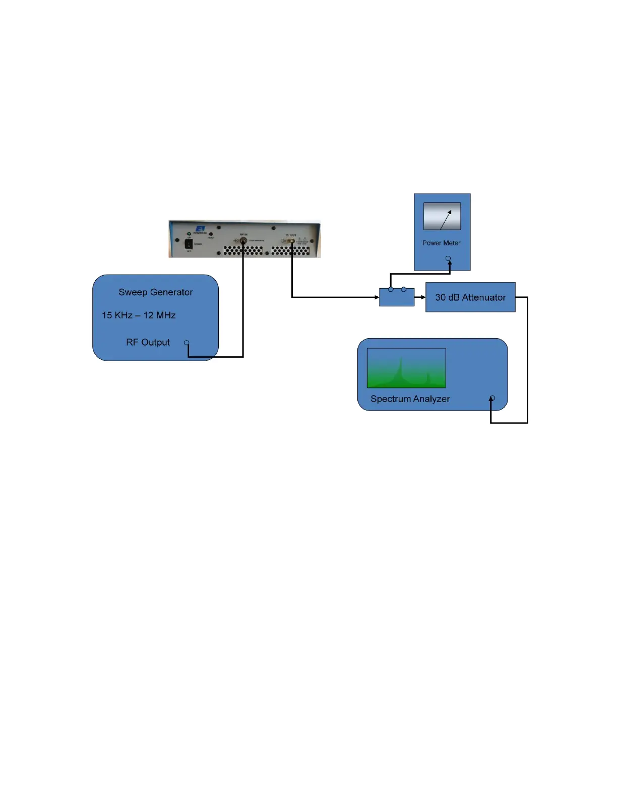
4.4.2 Measurement of Harmonics
Figure 4-2.
1.) Equipment Required:
a) Sweep/Signal Generator
b) Calorimetric Power Meter HP434A
c) Spectrum Analyzer.
d) Attenuator (20dB)
e) Attenuator (30dB)
f) Coupler (30 dB)
2.) Connect the Equipment as shown in Figure 4-2, then
proceed as follows:
a) Adjust the signal generator to a CW center frequency of 1 MHz, for an
indicated output of 10 watts on the power meter.
b) Using the spectrum analyzer, check that the level of the carrier
harmonics is less than -25 dB with respect to the carrier while manually
scanning the frequency band of 15 KHz to 12 MHz. An indicated power
output of 10W should be maintained during this operation.