26
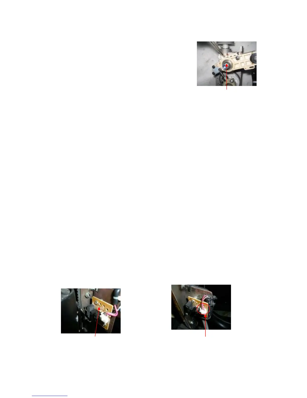
8.5 Disassembly of width inspection board
① Disassemble the rear cover of the back rest.
② Pull out the terminal of width inspection board.
③ Slacken and remove the screws tightening the width inspection
board to the reduction gear box with a plus screwdriver.
④ Remove the width detection board and a new one can be replaced.
Proceed in the reverse order of disassembly when assembling.
Tool: a plus screwdriver
Attention:In order to operate conveniently, you can disassemble the massage mechanism first, then the width
inspection board.
9. Replacement of up or down stroke photo-electricity assembly
① Disassemble the rear cover of the back rest.
② Pull out the terminal of the wire.
③ Slacken and remove the screw bolts tightening
the PCB of up or down stroke photo-electricity assembly
to the sheet-metal with a plus screwdriver and nipper pliers.
④ Proceed in the reverse order of disassembly when replacement needed.
Tools: a plus screwdriver and nipper pliers
Terminal of the
wire
Up stroke photo-
electricity assembly
Slacken and remove
the screws
 Loading...