Do you have a question about the Eastwood 51117 and is the answer not in the manual?
Thoroughly read and understand this manual before using the blaster. Learn applications, limitations, and hazards.
Blasters emit particles under high pressure. Adequate respiratory, eye, and body protection must be utilized at all times.
Use safety equipment. Eye protection (ANSI-approved safety glasses) is mandatory. Consider blast hood, hard hat, and hearing protection.
Ensure connections are tight. Do not defeat safety trigger. Store safely. Release pressure before opening tank. Check for damage.
Details the tank capacity for different models (#51117, #51118, #51119) and their abrasive media volume.
Specifies hose I.D., length, nozzle I.D., CFM requirements, and abrasive usage per hour.
Remove all components from the container and verify that they are present before starting assembly.
Attach the left and right tubular handle bars to the tank mounting tabs using screws and nuts.
Slide the axle through the handle bar ends and secure the wheels with washers and cotter pins.
Slide the front support leg over the stub welded to the front of the tank and secure with a cotter pin.
Attach the Air Inlet Tube to the Air Inlet Manifold/Moisture Separator and then to the tank's filler cap base.
Wrap threads with Teflon tape, install the pressure gauge into the inlet manifold, and attach the quick connect fitting.
Choose abrasive type and grit size (60 grit or finer recommended). Ensure abrasive is dry. Avoid silica-based abrasives.
Ensure abrasive is dry and clean. Use a sifter for dry media. Avoid media grit size > 60. Locate compressor away from dust.
Release pressure, remove filler cap, pour media using funnel, do not fill over 3/4 full, and securely re-thread filler cap.
Start with valves closed. Prevent clogs by following instructions. Set-up requires trial and error for optimal performance.
Connect air compressor to the inlet connector and open the air supply valve. Check for leaks.
Adjust Throttling Valve for velocity and Abrasive Control Valve for amount. Repeat adjustments for smooth, forceful flow.
Once flow is adjusted, begin blasting. Drain moisture trap frequently during use.
Hold safety trigger, close abrasive control valve, release trigger when only air flows, ensuring a clog-free system.
Point nozzle safely, expel material, close valves, disconnect air supply, and press trigger until gauge reads '0'.
Disconnect air, release pressure, unthread collar, remove nozzle and seal, then install new nozzle and tighten securely.
Disconnect air, release pressure, remove screw and nut, pull seal pad, insert replacement, and reattach screw and nut.
Drain water trap frequently during use and do not leave standing water when done blasting.
Keep blaster clean, release pressure after use, check for leaks, and inspect hose and fittings for wear.
Most issues stem from improper set-up. Adjust Throttling and Abrasive Control Valves for optimal smooth, forceful flow.
Caused by moisture or particle contamination. Remove source, drain trap, invert blaster, and sift media for reuse.
Ensure adequate compressor CFM output. Excessive hose length reduces CFM. Check compressor size if it runs constantly.
One-year warranty for manufacturing defects. Contact Eastwood for return authorization and include proof of purchase.
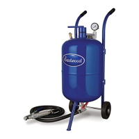
The Eastwood Abrasive Blaster is a robust tool designed for quickly and efficiently stripping away old paint, coatings, body fillers, accumulated dirt, and moderate to major rust, leaving a clean, bare metal surface ready for repair or painting. It is available in three models, distinguished by their tank capacity:
All models feature an 8 ft. x 1/2" I.D. hose length and operate within a working pressure range of 60-125 psi.
The abrasive blaster utilizes compressed air to propel abrasive media at high velocity, effectively cleaning and preparing surfaces. It features an Inlet Manifold Assembly with a moisture separator to ensure dry air delivery, a Throttling Valve for air pressure adjustment, and an Abrasive Control Valve for regulating media flow. The blast hose is equipped with a Safety Valve/Nozzle Assembly, which includes a "dead man valve" safety trigger to prevent accidental discharge.
The manual also provides troubleshooting steps for common issues like clumping media or insufficient CFM flow, emphasizing proper "tuning" and media management. A one-year warranty covers manufacturing defects, with specific instructions for returns and repairs.
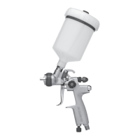
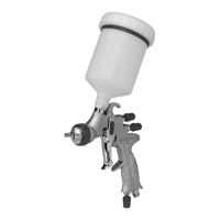
| Nozzle Size | 1.4mm |
|---|---|
| Fluid Adjustment | Yes |
| Material | Aluminum |
| Type | HVLP (High Volume Low Pressure) Spray Gun |
| Air Inlet | 1/4 inch |
| Recommended Compressor Size | 3 HP |