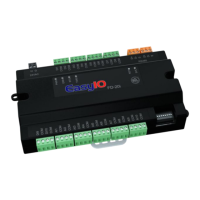
The EasyIO FD-20i Series is an affordable range of IO modules designed for various control applications. This series of controllers comes with a built-in bootloader program, enabling users to upgrade firmware without needing to send the device back to the factory. A key characteristic of the EasyIO FD-20i is its lack of an Ethernet port, relying solely on an RS485 serial port for communication. Firmware upgrades are performed via a direct serial connection to the controller.
Function Description
The EasyIO FD-20i controller serves as an input/output module, capable of handling both resistance-based universal inputs and voltage-free contact digital inputs. It is designed to integrate into building automation and control systems, facilitating data acquisition and control based on sensor readings and digital signals. The device supports Modbus RTU and BACnet MSTP protocols for communication over its RS485 serial port, making it versatile for different network environments.
Important Technical Specifications
Electrical Characteristics:
- Power Supply: The controller can be powered by either 24V AC (+/- 5%) or 24V DC (+20%/-15%). It is recommended to use an individual power supply for each controller to prevent damage to input/output devices and RS485 connections. If a single power supply is used for multiple controllers, ensure all power supplies are connected with the same polarity.
- Consumption: The device consumes less than 500 mA.
- Operating Temperature: It operates within a range of 32 to 150 Deg-F (0 to 65 Deg-C).
- Storage Temperature: The storage temperature range is -4 to 150 Deg-F (-20 to 65 Deg-C).
- Operating Humidity: The device is designed for non-condensing environments with 10% to 70% relative humidity.
- Universal Inputs (UI): The FD-20i features ten (10) non-isolated universal inputs. These inputs support either resistance measurements (e.g., thermistors, RTDs, potentiometers) or digital voltage-free contacts.
- Resistance Range: The working range for resistance inputs is 400 Ohm to 300 KOhms.
- Temperature Lookup Tables: When configured as a Thermistor type, the system provides 10 customizable temperature lookup tables for resistance-to-temperature translation. Common thermistor types like 10K and 10K with Shunt are supported. Temperature table selection is done via BACnet objects or Modbus registers, with the default for each UI channel set to table 1. The tables offer conversions to both Celsius and Fahrenheit for NTC 10K Type 2, NTC 10K Type 2 Shunt 11K, NTC 10K Type 3, NTC 10K Type 3 Shunt 11K, and NTC 20K.
- Digital Inputs (DI): The device also has ten (10) non-isolated voltage-free contacts digital inputs. These are mapped to DI 1 through DI 10. Additionally, the universal inputs (UI1-UI10) can be configured as digital inputs, mapping to DI 11 through DI 20, effectively providing up to 20 digital inputs if all universal inputs are used as such.
Communication:
- RS485 Serial Port: The FD-20i includes one physical RS-485 port, but provides two sets of RS-485 terminals for easy wiring.
- Termination: RS485 connections must be terminated at both ends with a 120 Ohm resistor.
- Wiring: Shielded twisted pair (STP) wire is recommended. Lightning protection circuits should be installed at one end of the wiring. The controller should be wired in a daisy chain network topology. Avoid long wire branches and limit the number of devices on a branch.
- Grounding: If a single power supply is used for all connected RS485 devices, ensure all devices share the same ground connection and that the same wire is used for the same terminal position (all "H" terminals connected to the same wire).
- Protocols: Protocol selection (Modbus RTU or BACnet MSTP) is done via DIP switch 1.
- Baud Rate: Default Baud Rate for Modbus is 19.2K (even parity, 8 data bits, 1 stop bit). Default Baud Rate for BACnet is also 19.2K.
- Serial Address: The serial address is set using DIP switches 2 through 8, utilizing a binary bit system where DIP 8 is the Least Significant Bit (LSB) and DIP 2 is the Most Significant Bit (MSB).
Usage Features
- DIP Switch Configuration: DIP switches are used for critical configurations such as protocol selection (Modbus RTU or BACnet MSTP) and setting the serial address of the device. The white spot/square on the DIP switch represents the toggle button.
- LED Indicators: The device includes several LEDs to provide status information:
- PWR (Power): Indicates the presence of 24VAC power source and internal power.
- ERR (Error): Indicates communication errors.
- STS (Status): Shows the heartbeat of the Microcontroller, blinking at 1-second intervals during normal operation.
- TXRX (Transmit/Receive): Indicates communication activities (transmitting or receiving) on the communication port.
- Buttons:
- Reset Button: Toggling this button performs a hardware reset of the controller.
- Service Button: Activates the built-in bootloader program, which is used for software upgrades.
Maintenance Features
- Firmware Upgrade: The built-in bootloader program allows users to upgrade the firmware via a direct serial connection, eliminating the need to send the device back to the factory for software updates.
- Troubleshooting with LEDs: The LED indicators (PWR, ERR, STS, TXRX) provide immediate visual feedback on the device's operational status, power supply, communication health, and microcontroller activity, aiding in quick diagnosis of issues.
- Technical Support: For technical issues, EasyIO provides dedicated support channels via email for Worldwide and Asia Pacific, Americas, and Europe regions.