EasyIO FD-20i User Reference v1.2
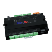
Buttons and Indications
The controller will perform a hardware reset when the Reset Button is toggle.
The Service button is used to activate the built-in bootloader program for software upgrade.
Each digital output has a correspondence LED to indicate its current state.
Button and LED indications
PWR is used to indicate the presence of
24VAC power source, and internal power
ERR is to indicate whenever there is
communication errors.
STS is used to indicate the heartbeat of the
Microcontroller. The STS LED will blink at
1-second interval in normal operation
condition.
TXRX is used to indicate when there are
communication activities (Transmitting or
Receiving) on the communication port.
Technical Support
For technical issue, please contact
Worldwide and Asia Pacific Support : support@easyio.com
Americas Support : support@easyio.pro
Europe Support : support@easyio.eu
 Loading...