20
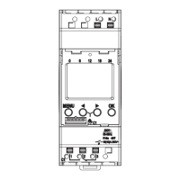
Control Valve
Mount
Trunnion
O-ring
Shims
Shims
O-ring
Figure 24
72 Install the trunnion bolts and tighten them to the
specified torque given below:
69 Carefully, put the swashplate, cylinder barrel, and
shaft into the motor housing. Be sure the feedback
linkage is by the control valve mount.
70 Lubricate and install a new o-ring on each trunnion.
71 Install the trunnions and shims in their original
locations.
Strike the Trunnion to Free-up
Swashplate Movement
Spring
Compression
Scale
Model Number Trunnion Bolt Torque
33, 39 28 lb-ft [38 Nm]
46, 54, 64 44 lb-ft [60 Nm]
73 After the bolts are torqued strike one of the trunnions
to free up the swashplate’s movement.
74 Measure the swashplate breakaway force with a
spring compression scale. Attach the scale to the
feedback linkage as shown in figure 25. A swashplate
breakaway force of 2 to 5 lb [,9 to 2,3 Kg] is required.
Add or subtract trunnion shims as needed.
Figure 25
Important: The trunnion shims on
each side of the motor should be
equal thickness. The maximum
allowable difference between the
sides is .010 in. [,3 mm].
2
2
Major Repairs: Trunnions and Servo Pistons

 Loading...