27
Bolt (4)
Back-up Ring
O-ring
Sq. Cut Seal
Valve Block
Hose Fittings
Hose Ass'y
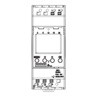
Figure 37
Control Valve
Gasket
Feedback
Linkage
Figure 38
104 Install new o-rings and back-up rings in the grooves
around the high pressure ports as shown in figure 37.
Install a square-cut seal in the groove around the low
pressure port. Use petroleum jelly to hold these sealing
rings in place while the valve block is installed.
105 Position the valve block on the motor. Install the
four hex head bolts and tighten them to 28 lb-ft [38 Nm].
106 Tighten the high pressure relief valves to 25 lb-ft
[34 Nm].
Tighten the low pressure relief valve, and shuttle valve
plugs to 80 lb-ft [108 Nm].
Tighten the gauge port plugs and control pressure hose
fittings, if used, to 17 lb-ft [23 Nm].
107 Connect the control pressure hose between the
motor housing and valve block fittings, if used. Tighten
both ends to 7.5 lb-ft [10 Nm].
108 Reposition the motor so the control valve mount is
on top.
109 Place a new control valve gasket on the motor.
110 Connect the feedback linkage and position the
control valve on the motor.
Important: When the control valve is positioned on the
motor make sure the feedback linkage points towards
the end cover.
111 Install the six hex head bolts and tighten them
finger tight.
112 Move the control lever back and forth; it should
move freely in both directions and self-center. If it
doesn’t, recheck the feedback linkage.
113 Tighten the six hex head bolts to 16 lb-ft [22 Nm].
Note: The control pressure hose is now obsolete. Poor
motor control characteristics may be experienced when
the motor gets control pressure from the valve block. It
is best to run a separate control pressure line from the
charge pump to the motor. If possible re-plumb the
application so the control pressure hose is no longer
used. Be sure to plug the port in the valve block.
End Cover, Valve Block and Control Valve

 Loading...