24 OPERATION AND INSTALLATION INSTRUCTIONS MN280075EN July 2018
Form 6 microprocessor-based rack-mount recloser control
FORM 6 RACK MOUNT
RECLOSER CONTROL
REMOTE BOX
Not All Remote
Connections
Shown
SHIELD
11
13
12
CO1
CO1
Recloser
Status
3
5
7
4
6
8
CI1
CI2
CI3
CI1
CI2
CI3
Remote
Trip and
Lockout
Supervisory
Trip and
Lockout
Supervisory
Close
A*
B*
TB1
Typical Customer Supplied
Whetting Voltage
*Contacts shown
with recloser in
OPEN position.
48/125 VDC
or
120 VAC
–+
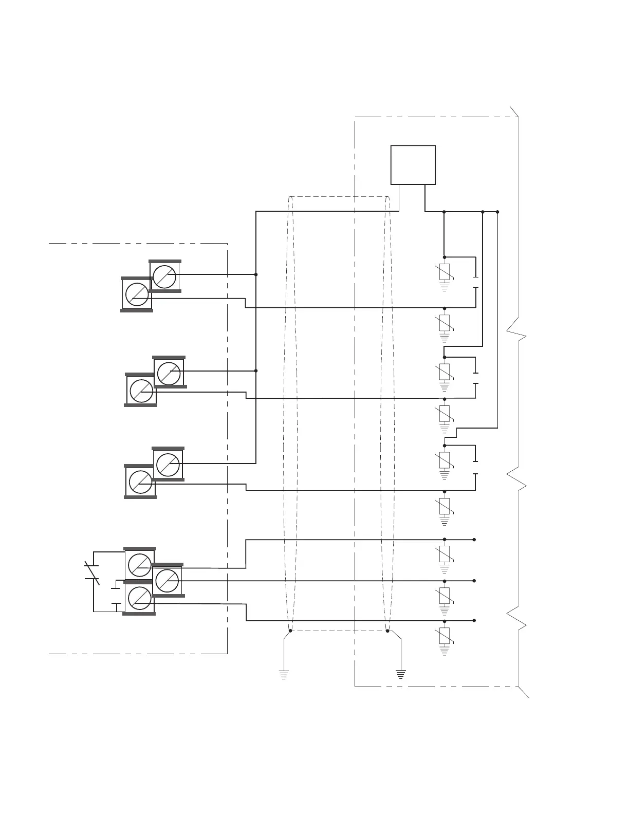
A Single common wire can be used for multiple inputs
if it is jumpered at the I/O board terminals.
NOTES: Arresters to be metal oxide varistors (MOVs) 320 VAC,
150 Joules or equivalent.
Shielding for Supervisory Cables should follow
the representative input control contacts and
output status contacts as shown.
External lead resistance must not exceed 200 ohms.
Supervisory and Remote Functions are
default functions.
Figure16. Shielding and surge protection for supervisory and remote cables (48-125 VDC, 120 VAC option)
 Loading...


