133
127
120
115
110
104
G
RCT
2
133
127
120
115
110
104
G
RCT
1
RCT
2
1 2 3 4 5 6 7
Cable Assembly,
Control Box
JBB-G
RLS-1
JBB-NL
JBB-HS
LLS-1
JBB-DHR
G HS NL
D
H
R
R
1
L
1
V
S
V
5
V
4
V
7
R
2
L
2
R
4
C
3
G
TB
1
TB
2
-C
1
SD
1
-2
PD
2
-2
TB
1
-G
TB
8
-4
TB
2
-G
TB
2
-BR
TB
1
-R
1
TB
1
-L
1
TB
2
-V
7
TB
1
-V
4
RCT
1
-G
RCT
2
-G
RCT
1
-G
RCT
2
-G
RCT
1
-120
TB
2
-DHR
TB
2
-L
3
TB
2
-R
3
TB
8
-3
TB
1
-G
TB
2
-V
S
TB
2
-NL
TB
2
-HS
TB
8
JBB-C
1
G R
1
L
1
V
5
G L
4
C
2
C
4
C
4
TB
1
-DHR
TB
1
-L
1
TB
1
-HS
SD
1
-3
TB
8
-4
TB
8
-5
RCT
2
-120
TB
2
-G
TB
1
-NL
TB
1
-R
1
TB
1
-C
3
TB
2
DHRNLHS L
3
R
3
C
3
C
1
V
M
V
S
V
7
V
9
G
BRJ56
78
G V
S
TB
1
-VS
TB
2
-J
RCT
1
SD
1
PD
1
PD
2
11 1 2
2
2 3 4
TB
8
-1
JBB-S
6
JBB-S
7
Motor Capacitor
1 2
(V6) (V1)
(C)
TB
2
-C
3
TB
1
-G
JBB-S
4
JBB-S
2
JBB-C
2
TB
2
-C
2
PD
1
-2
JBB-G – White
JBB-HS – Orange
RLS-1 – Blue
LLS-1 – Green/Black
JBB-NL – Red/Black
JBB-DHR – Orange/Black
JBB-S
6
– Blue/Black
JBB-S
7
– Black/ White
JBB-S
4
– White /Black
JBB-S
2
– Black
JBB-C
1
– Red
JBB-C
2
– Green
TB
1
-G – White
TB
2
-HS – Orange
TB
2
-R
3
– Blue
TB
8
-1 – Blue
TB
2
-L
3
– White /Green
TB
8
-3 – White /Green
TB
2
-NL – White /Red
TB
2
-DHR – White /Orange
TB
2
-VS – Black
RCT
1
-120 – Black
TB
1
-G – White
RCT
2
-G – White
SD
1
-2 – Violet
TB
2
-C
3
– Green
RCT
2
– White /Brown
RCT
1
– Black
TB
2
-C
1
– Red
PD
2
-2 – White /Brown
TB
2
-V
7
– White /Brown
RCT
1
-G – White
TB
1
-G – White
PD
1
-2 – Black
TB
1
-V
4
– Black
RCT
2
-G – White
TB
8
-4 – White
TB
1
-R
1
– Blue
TB
1
-L
1
– White /Green
TB
2
-G – White
RCT
1
-G – White
TB
2
-BR – White /Blue
TB
2
-G – White
RCT
2
-120 – White /Brown
TB
8
-5 – White /Blue
TB
8
-4 – White
TB
2
-J – White
TB
1
-VS – Black
SD
1
-3 – Red
TB
1
-C
3
– Green
TB
1
-HS – Orange
TB
1
-R
1
– Blue
TB
1
-L
1
– White /Green
TB
1
-NL – White /Red
TB
1
-DHR – White /Orange
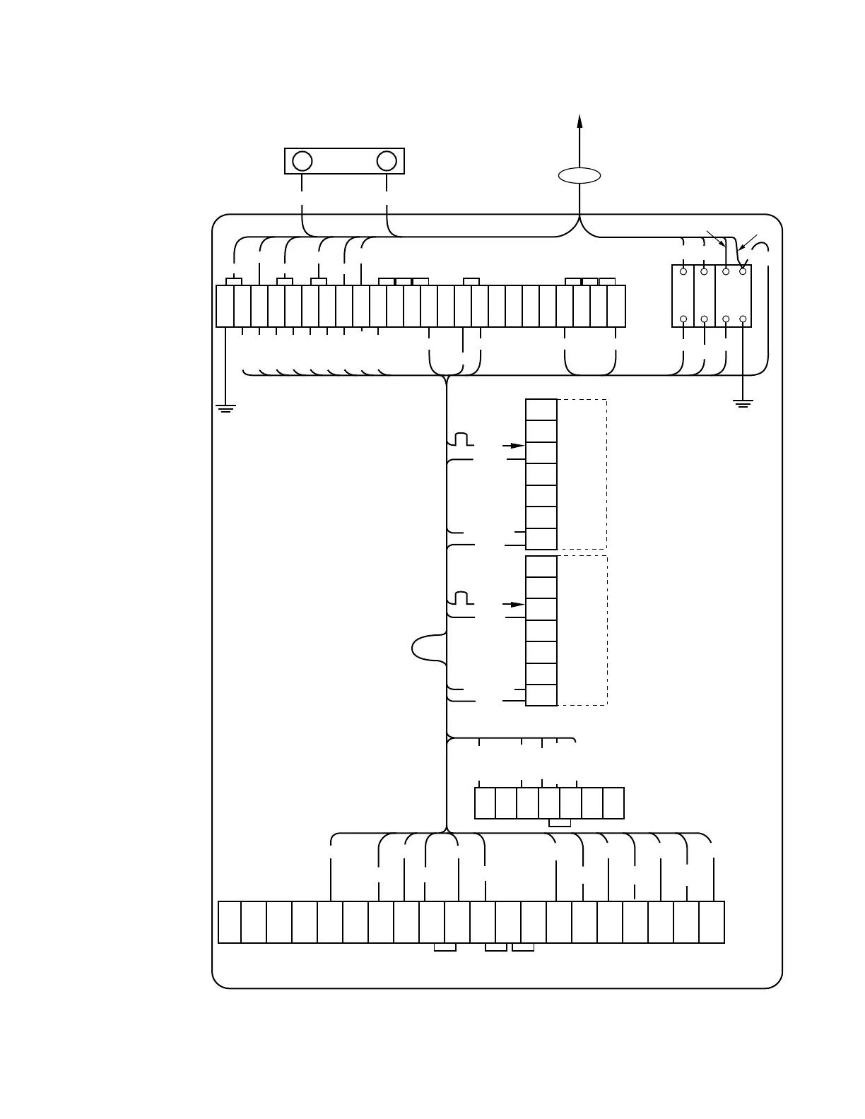
Note: TB
2
-V
7
to TB
2
-V
s
jumper
only applies to non-reverse
power flow back panel
assemblies supplied without
RCT
2
.
TB
2
-V
7
is connected to RCT
2
-
120 on back panel assemblies
set up for reverse power flow
supplied with RCT
2
.
Figure 10-5. Back panel signal circuit.
118
CL-6 SERIES CONTROL INSTALLATION, OPERATION, AND MAINTENANCE INSTRUCTIONS MN225016EN January 2016
 Loading...


