27
SPEAR™ Single-Phase Recloser System
INSTALLATION AND OPERATION INSTRUCTIONS MN280048EN June 2016
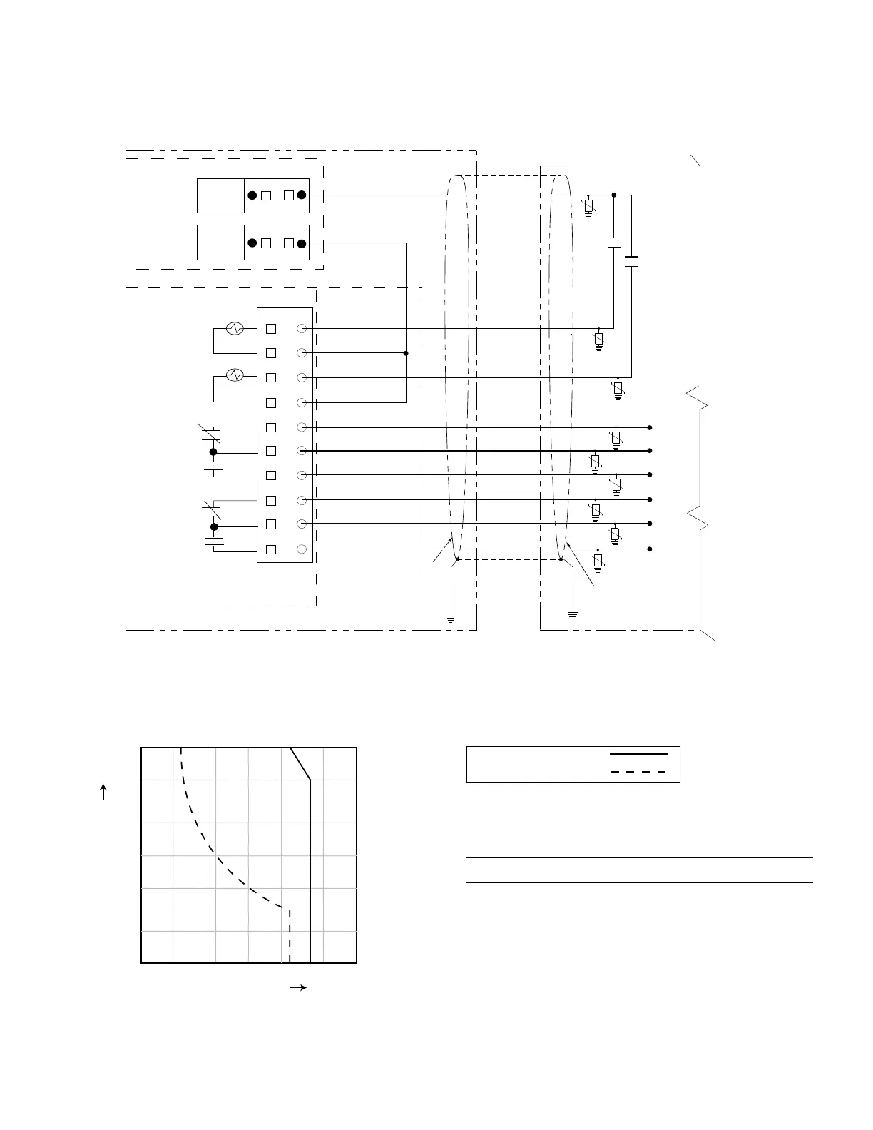
Figure 24.
SPEAR CONTROL
Remote Terminal Unit (RTU)
Not All
Remote
Connections
Shown
Contact I/O
Module
I/O
Recloser Trip and Lockout
Recloser Close
Supervisor ON/OFF Status
(OFF)*
Recloser Status
(Closed)
6
5
4
3
2
1
VTC OUT
WET +
WET —
Control-Supplied
Whetting Voltage
24 VDC
Shield
Shield
CO4-NO
CO3-NO
CO3-NC
CO3-COM
CO4-NC
CO4-COM
* Relay contacts shown for indicated status. This is also the de-energized state.
10
9
8
7
Customer connections to Contact I/O module with shielding and surge protection (I/O functionality
shown is factory-default for the module)
Figure 25.
10
5
2
1
0.5
0.2
0.1
10 20 50 100 200 500
Current (A)
Voltage (V)
Maximum Switching Power
AC Resistive Load
DC Resistive Load
Maximum output switching graph
AC Resistive Load:
DC Resistive Load:
Legend
NOTICE
External leads must be shielded and the shield must be
grounded at both ends. Terminate each lead with a 320 VAC,
150 Joules metal oxide varistor (MOV), or equivalent, at the
remote end. Attach MOV’s between the leads and ground.
Failure to properly shield and protect leads can result in
equipment damage and/or unintentional operation.
 Loading...


