Table 11. Communication support equipment
Description Catalog number
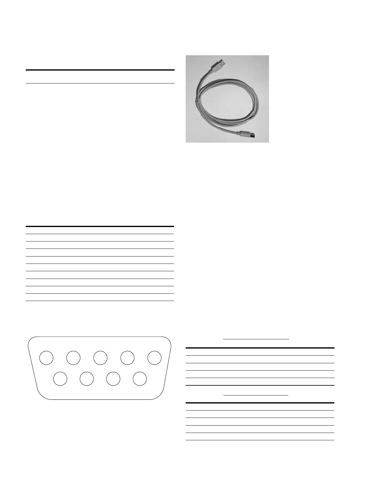
USB cable, Type A male-to-Type B male
connectors, 2 meters (6.5 ft.) length
KME4D-66
RS-232 serial communication card
The RS-232 Serial communication card accessory provides
means for establishing asynchronous link-based digital
communications with the Form 4D pole-mount control.
The Galvanic isolated (1000 VDC) RS-232 port can operate
at communication speeds up to 256 kbps. The accessory
also includes TX and RX indicating LEDs for verifying
communications.
Digital communications must be programmed to ensure
proper operation of the RS-485 communication card
accessory. Refer to S280-104-2 Form 4D Control Programming
Guide for additional protocol support information.
Table 12 indicates the pin assignments for the side panel
RS-232 communication port (Figure 26). Refer to Figure 29
for pin identification.
Table 12. RS-232 Serial communication port pin
Assignments
Pin number Signal name
1 DCD Carrier Detect
2 RXD Receive Data
3 TXD Transmit Data
4 DTR Data Terminal Ready
5 GND Signal Ground
6 DSR Data Set Ready (Not Connected)
7 RTS Request to Send
8 CTS Clear to Send
9 NC Not Used
10 (Shroud) Chassis Ground
J2 DB-9 Connector
1 2
3
4 5
6
7
8 9
Figure 28. RS-232 Serial communication port pin
identification
Figure 29. USB cable
RS-485 serial communication card
The RS-485 serial communication card accessory provides
means for establishing asynchronous link-based digital
communications with the Form 4D pole-mount control.
The Galvanic isolated (1000 VDC) RS-485 port is 1/8 unit
load, which allows for up to 256 devices on the bus. The
accessory has selectable 2-wire or 4-wire modes (half- or
full-duplex) via a switch on the board. Also on the board are
selectable 120 ohm termination resistors, which should be
used when the device is at the physical end of a bus. The
accessory has a maximum communication speed of 1 Mbps.
ote:N The terminating resistors included on the Form 4D
control RS-485 interface card have been specified
for +/- 5 Volt DC RS-485 installations. For RS-485
applications using a voltage supply greater than
5VDC, external terminating resistors must be used.
Digital communications must be programmed to ensure
proper operation of the RS-485 communication card accessory.
Refer to S280-104-2 Form 4D Control Programming Guide for
additional protocol support information.
Table 13 indicates the pin assignments for the RS-485 serial
communication card accessory (Figure 30).
Table 13. RS-485 serial communication port
pinassignments
4-Wire operation (full-duplex)
Pin number Pin name Pin description
1 TX+ Transmit, Non-Inverting
2 TX– Transmit, Inverting
3 RX– Receive, Inverting
4 RX+ Receive, Non-Inverting
5 GND Signal Ground
2-Wire operation (half-duplex)
Pin number Pin name Pin description
1 TX Transmit
2 RX Receive
3 RX Receive (internally connected to pin 2)
4 TX Transmit (internally connected to pin 1)
5 GND Signal Ground
34 OPERATION INSTRUCTIONS MN280049EN September 2017
Form 4D Microprocessor-based pole-mount recloser control installation and operation instructions
 Loading...


