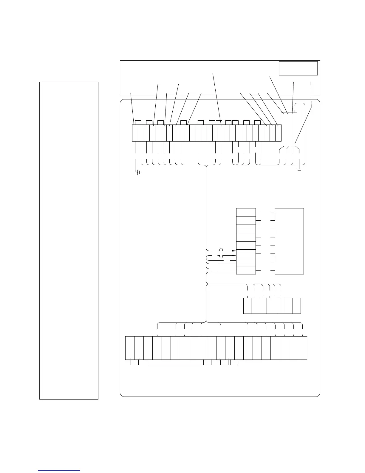
Figure 9. CRA kit back panel wiring for GE voltage regulator.
27 30
26 & 10
10
(16 AWG)
28 29
G G
R R L L
O
H
G G
C
D
R
N
L
H
S
#
2
N
L
H
S
GE Wiring Connections
#
1
V
2
5
1
4
C
2
C
3
2
0
2
1
2
2
V V V
1
2
4
5
6
7
28 9 8 3
2 12
23 10
11 14
27
13
23
17
15 16
TB1
V
6
V
1
c
13
36
30
31
32
33
34
35
37
RCT1
30
27
25
23
21
20
120
COM
8
7
6
5 J
V9
V7 BR G G VS VS VM C1 C3 HS
R3 L3
NL H
D
R
28 29
27
20
19
11
15
14
3
4
6 8 9
1 2
3
4
5
6
7
TB8
5
29
7
18 19 20
12
25
25
17
TB2
32
(20 AWG)
Pos Gnd
20 or 21 or 22
31
L
N
2
10
18
222120
Wire Color Code
1 White
2 White
3 Orange
4 Blue
5 Blue
6 White/Green
7 White/Green
8 White/Red
9 White/Orange
10 Black
11 Black
12 White
13 Violet
14 Green
15 Red
16 Red
17 Black
18 White
19 White
20 White/Blue
21 White/Blue
23 White/Brown
24 White
25 Black
26 White/Brown
27 Brown
28 Brown
29 Red/Black
30 Blue
31 Green
32 Yellow
33 Orange
34 Red
35 Brown
36 Black
37 White
ote:N If the color codes does not match, check Table 2, matching with lead number identifications. There have been several
different color code identifications use by GE over the years. If ID label numbers are used, they should apply no
matter what color code system was used by GE.
11CL-7 control replacement assembly installation instructions and service information MN225017EN October 2016
 Loading...


