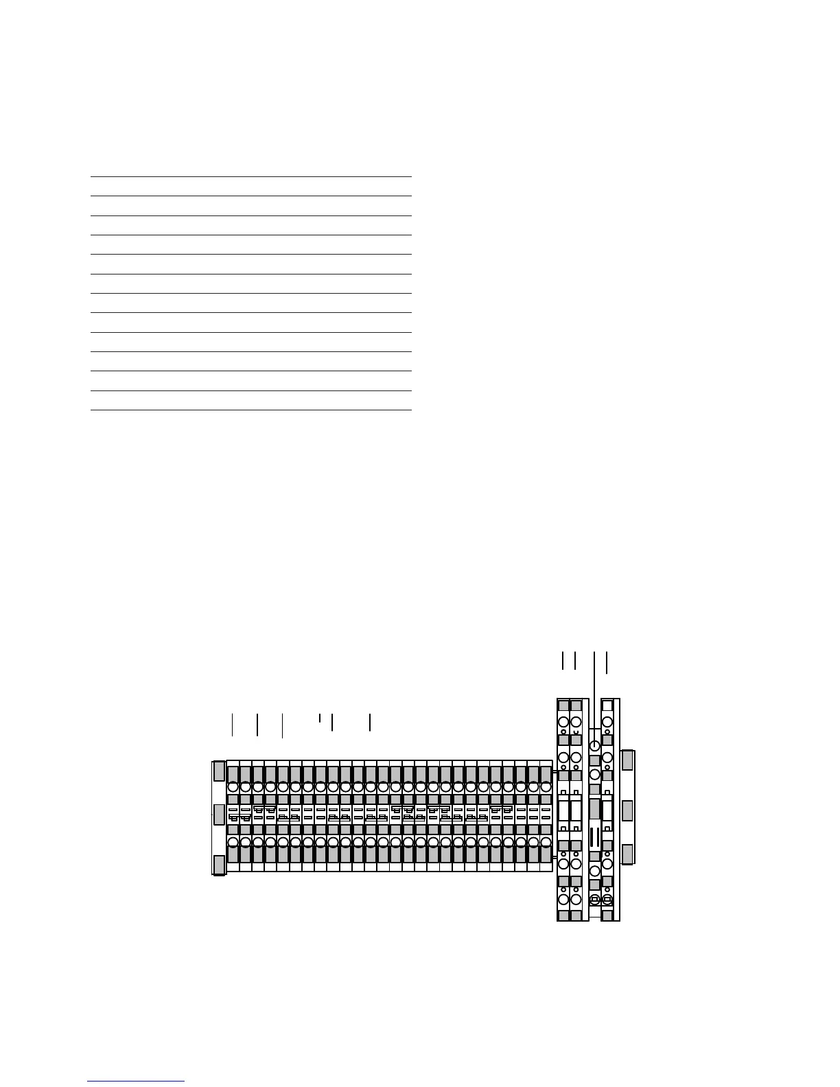
Figure 13. TB1 Eaton's connections.
(G)
(R)
(R)
(L)
(L)
(OC)
(DHR)
(NL)
(NL)
(NL2)
(HS)
(HS)
(#2)
(G)
(G)
(#1)
(V2)
(V5)
(V1)
(V4)
(C2)
(C3)
(20)
(21)
(23)
(G)
(V6)
(V1)
(C)
White - Ground
Blue - Raise
Green/Black - Lower
Orange/Black - Drag Hand
Red/Black - Neutral Light
Orange - Holding Switch
Black - Load PT
Green - CT Positive
Red - CT Negative
Table 4. CRA Kit Connections for Eaton/McGraw
Edison Voltage Regulators
Connection Point Wire Color
V1 Black
G White
C (bottom) Red
C (top) Green
HS Orange
R1 Blue
V6 White/Black
NL Red/Black
L1 Green/Black
DHR Orange/Black
Motor Cap 1 Lt Blue/Black
Motor Cap 2 Black/White
17CL-7 control replacement assembly installation instructions and service information MN225017EN October 2016
 Loading...


