Catalog data MN650002EN
Effective February 2019
Deadbreak apparatus connectors
Step 10.
Check di men sions
•
Check length from end of com pres sion con nec tor to top
of cable adapter.
•
Length should be be tween 6 3/4" and 7 3/4"
(171 - 197 mm). (Re fer to Fig ure 23.)
Install BOL-T T-body with mating parts
Step 11.
Install DT635 T-body
•
Clean and lubricate outside of cable adapter with lubricant
supplied.
•
Clean and lubricate inside of T-body with lubricant
supplied.
ote:N If test point T-body is used, insure test point is
opposite front plate side of T-body.
•
Without moving the cable adapter, slide T-body onto cable
adapter until compression connector eye is centered in
600 A interfaces. (Refer to Figure 24.)
ote:N The end of the cable adapter must line up with
the top edge of the tape marker after T-body
assembly. Refer to Figure 21.
•
Remove tape marker from cable.
•
Go to Step 12, page 13 to complete T-body termination.
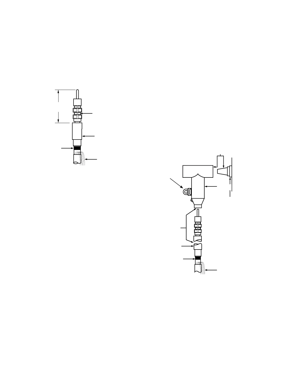
Figure 23. Line illustration for dimensional check.
6 3/4" - 7 3/4"
(171-197 mm)
Cable
adapter
Concentric
neutral wires
Tape
marker
Compression
connector
Figure 24. Line illustration of BOL-T T-body installation.
T-body
Cable adapter
Tape marker
Concentric neutral wires
Lubricate
600 A Interfaces
Apparatus
bushing
Test point on
accessible
side
12
600 A 35 kV class BOL-T connector assembly installation instructions for MN650002EN February 2019
 Loading...


