3. Remove the stationary contact from the contact
assembly panel. See Figure 79.
4. Install the new stationary contact into the mounting
holes in the contact assembly board for the contact
being replaced. See Figure 80.
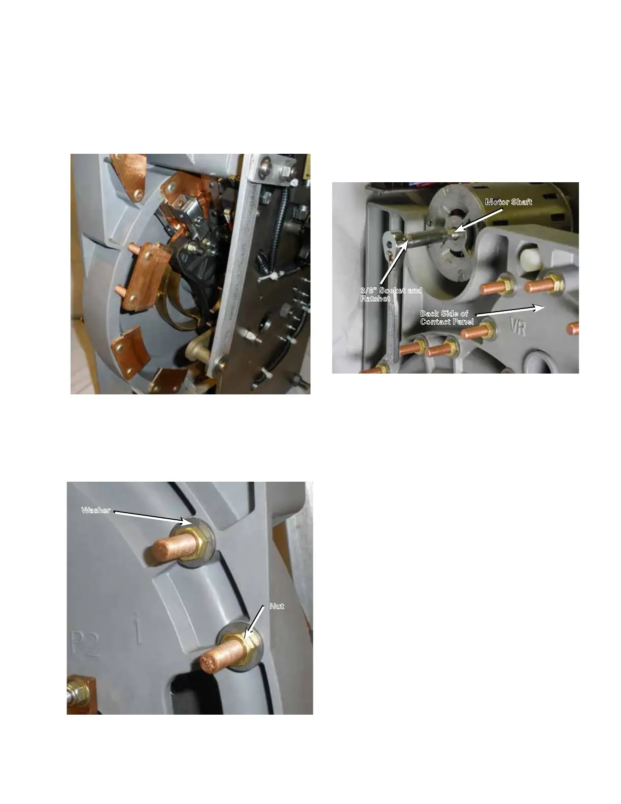
5. Place a flat washer and nut on each stud. Use a 9/16"
deep-well socket and ratchet to tighten the nuts. Using
a torque wrench, tighten the nuts to a torque of 80–90
in-lbs (9.0–10.2 Nm). See Figure 81.
6. Repeat Steps 1 through 5 for each stationary contact to
be replaced.
7. When the movable contacts are located on the
stationary contact to be replaced, the movable contacts
must be moved. Place a 3/8" socket onto the rear shaft
of the motor. See Figure 82. Using a ratchet, rotate
the motor to position the movable contacts off of the
contact to be replaced.
8. Once the work has been completed, place the tap-
changer in the neutral position.
Figure 81. Contact hardware installation.
Nut
Washer
Figure 82. Motor and movable contact rotation.
Motor Shaft
Back Side of
Contact Panel
3/8" Socket and
Ratchet
Figure 80. Stationary contact removal.
31
QD5 QUIK-DRIVE TAP-CHANGER INSTALLATION AND MAINTENANCE INSTRUCTIONS MN225012EN March 2016
 Loading...


