EasyManuals Logo

Eaton 600 A 15 kV class push-OP Installation Instructions

Eaton 600 A 15 kV class push-OP
24 pages
To Next Page IconTo Next Page
To Previous Page IconTo Previous Page
Page #10 background imageLoading...
Page #10 background image
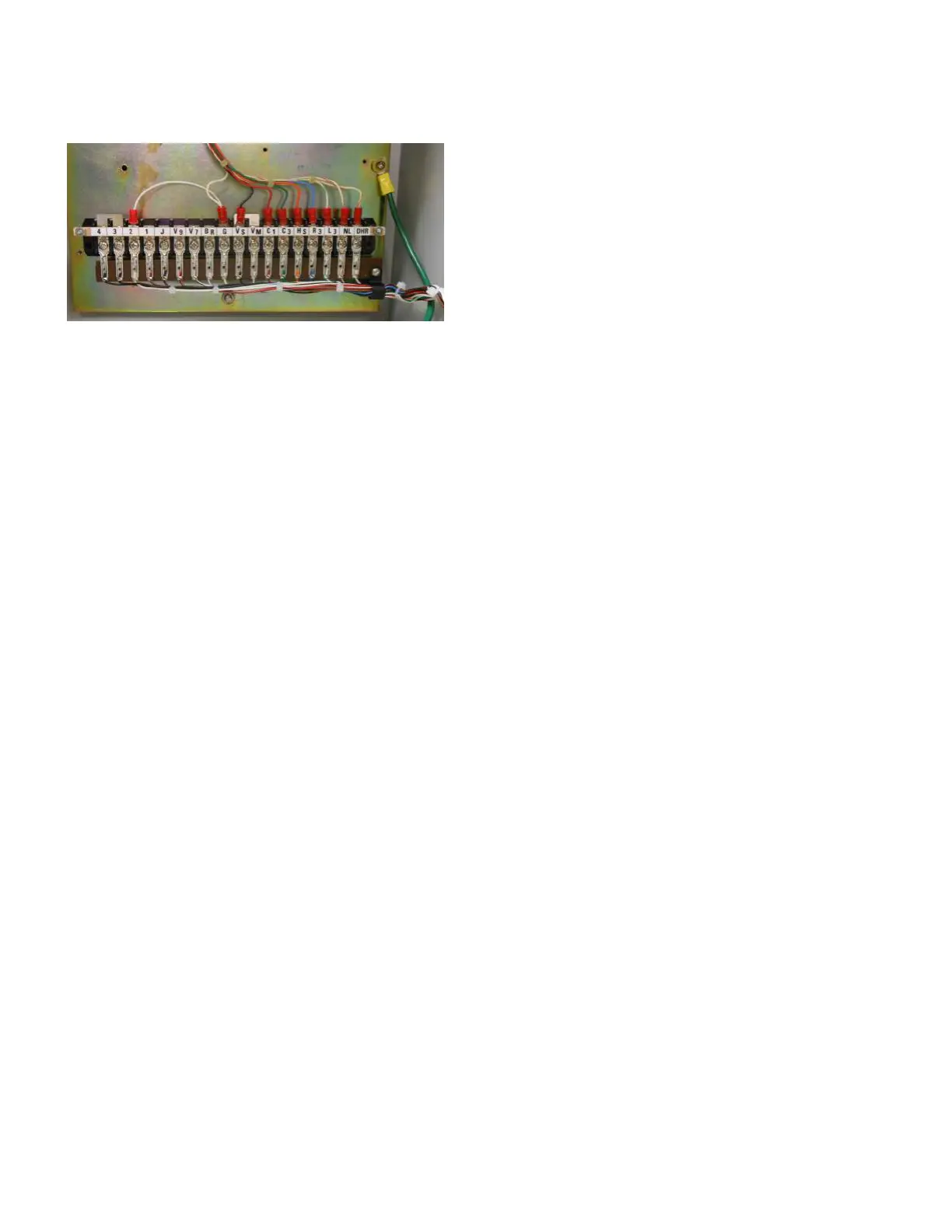
Figure 15. Fanning strip installed into terminal board
13. Secure the CL-7 control panel to the latch tab using the
latching screw.
14. Complete the control programming and testing as
required. Refer to document MN225003EN, CL-7
Control Installation, Operation, and Maintenance
Instructions for proper control configuration and start
up procedures.
6
CL-7 Control Panel Retrofit
InstallatIon InstructIons MN225018EN April 2018

Other manuals for Eaton 600 A 15 kV class push-OP

Questions and Answers:

Question and Answer IconNeed help?

Do you have a question about the Eaton 600 A 15 kV class push-OP and is the answer not in the manual?

Eaton 600 A 15 kV class push-OP Specifications

General IconGeneral
BrandEaton
Model600 A 15 kV class push-OP
CategoryCables and connectors
LanguageEnglish

Related product manuals