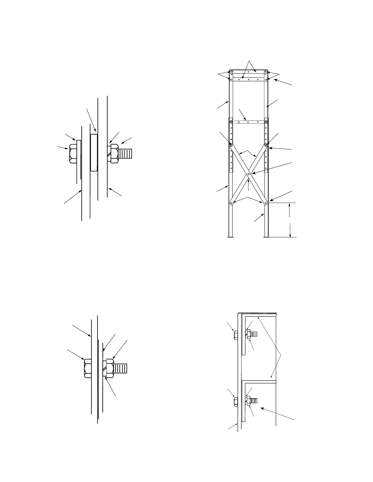
3. Attach the upper ends of the short cross braces
(Item6) to the upper posts (Items 2 and 3) and lower
posts (Items 4 and 5). Use 1.75” hex head capscrews
(Item 11), with a spacer (Item 16) between the upper
and lower posts. Secure with lockwashers (Item 14)
and .5” hex nuts (Item 13). See Figures 7 and 9.
4. Attach the lower ends of the short cross braces (Item6)
to the lower posts (Items 4 and 5) with 1.25” hex head
capscrews (Item 9), and secure with lockwashers (Item
14) and .5” hex nuts (Item 13). See Figures 8 and 9.
5. Attach the short cross braces (Item 6) at their midpoint
with 1.25” hex head capscrews (Item 9), and secure
with lockwashers (Item 14) and .5” hex nuts (Item 13).
See Figure 8 and 9.
6. Attach two support angles (Item 1) to the upper ends of
the upper posts (Items 2 and 3) and one support angle
on the control side of the assembly with 1.25” hex
head capscrews (Item 9), and secure with lockwashers
(Item 14) and .5” hex nuts (Item 13). See Figures 9 and
10. Place control-support angle 533mm (21“) above
lower support angle, measured screw to screw.
Figure 9. Assembling narrow side of frame.
9, 13, 14
9, 13, 14
3
6
2
4
5
400mm (15.75 in)
9, 13, 14
11, 13, 14, 16
11, 13, 14, 16
1
Step 3
Step 4
Step 5
Step 6
Figure 7. Attaching short cross brace (Item 6).
11
6
16
14
13
LOWER
POST
(Items 4 or 5)
UPPER
POST
(Items 2 or 3)
Figure 8. Assembling frame with Items 9, 13, and 14.
FRAME
9
FRAME
13
14
Figure 10. Attaching support angle (Item 1) to upper
post.
9
ANGLE SUPPORT
(Item 1)
14
13
UPPER
POST
9
14
13
Control-side
only
8 SUBSTATION FRAME KNOVA59-1 AND KNOVA59-3 ASSEMBLY AND INSTALLATION INSTRUCTIONS MN280043EN January 2016
 Loading...


