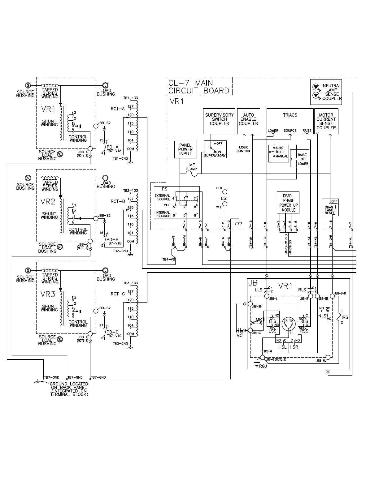
EasyManuals Logo

Eaton 600 A 15 kV class push-OP User Manual

Eaton 600 A 15 kV class push-OP
188 pages
To Next Page IconTo Next Page
To Previous Page IconTo Previous Page
Page #180 background imageLoading...
Page #180 background image
DHR Drag Hand Reset
EST External Source Terminals
HSL Holding Switch Lower
HSR Holding Switch Raise
IRS Indicator Reset Solenoid
(Position Indicator)
JB Junction Box on the Regulator
Cover
JBB Junction Box Terminal
Board on the Cover
ote:N Portion of schematic shown in dotted
enclosures is located in regulator tank.
Figure 64. Multi-phase motor schematic
172
INSTALLATION, OPERATION, AND MAINTENANCE INSTRUCTIONS MN225003EN April 2018
CL-7 Voltage Regulator Control

Table of Contents

Other manuals for Eaton 600 A 15 kV class push-OP

Questions and Answers:

Question and Answer IconNeed help?

Do you have a question about the Eaton 600 A 15 kV class push-OP and is the answer not in the manual?

Eaton 600 A 15 kV class push-OP Specifications

General IconGeneral
BrandEaton
Model600 A 15 kV class push-OP
CategoryCables and connectors
LanguageEnglish

Related product manuals