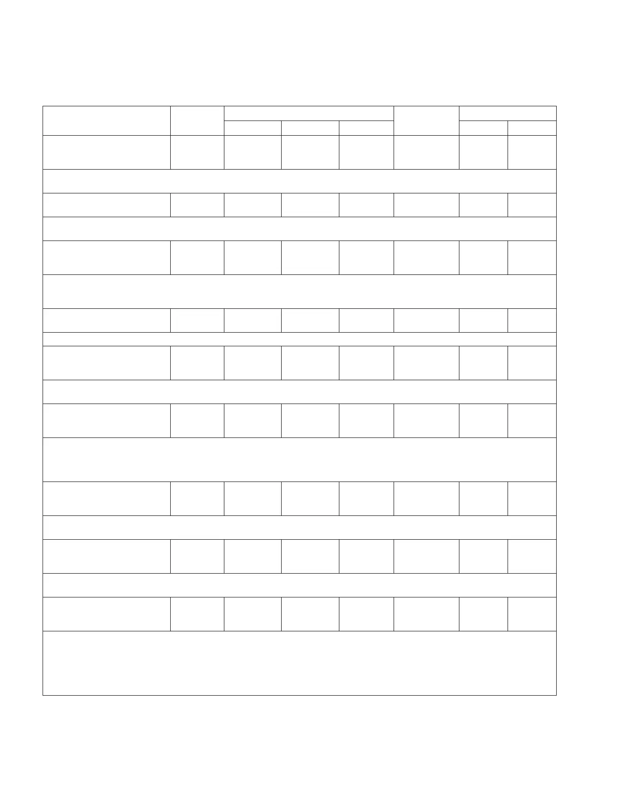
Table10. Function codes (continued)
Parameter
Unit of
Measure
Security Level
Default Value
Key Entry Limit
To Read To Write To Reset Low High
327 PMT Mode B
Current Limit
XXX %
% View Modify NA 50 0 160
•The PMT Mode B is enabled at or below the current limit setting, defined as a percentage
of the CT primary rating.
328 PMT Mode B
Issue Test
--- NA Modify NA NA NA NA
•The user can force the PMT Mode B operation independent of the time-delay setting.
•The test is initiated by pressing ENTER and then ENTER again to confirm the command.
333 Contact Duty
Cycle Monitor
XX.XXX %
% View NA NA NA NA NA
•The contact life Duty Cycle Monitor function represents the amount of life consumed, for
the worst-case contact, displayed as a percentage of total life. Individual contact wear
levels can be interrogated via the ProView NXG software.
410 Leader/Follower
Off
--- View Modify NA Off NA NA
•This will turn On or Off Leader/Follower feature. The options include: Off; On.
411 Leader/Follower
State
Not Ready
--- View NA NA NA NA NA
•This is the state of the Leader/Follower function. Display include: Ready; Not Ready;
Active; Inactive; Unable To Operate; Loss Of Comms; Unknown.
412 Leader/Follower
Mode
Lead Phase Reg.
--- View Modify NA
Lead Phase
Reg.
NA NA
•Designates the mode of operation for the Leader/Follower feature. Options include: Lead
Phase Reg.; Volt Averaging Reg.; Max Deviation.
•See Section 7: Advanced Control Features: Leader/follower scheme for more information of
the various modes of operation.
413 Leader/Follower
Designation
Follower 1
--- View Modify NA Follower 1 NA NA
•This is the Leader/Follower table designation for each connected regulator. The options
include: Leader; Follower 1; Follower 2.
414 Follower Devices
Configured
1
--- View Modify NA 1 1 2
•The number of follower devices connected in a Leader/Follower scheme. The allowable
options are 1 or 2.
415 Leader/Follower
Tap Wait Timer
XXXXX mSec
MilliSec View Modify NA 0 0 10000
•Sets a wait timer for use with Leader/Follower gang operation. Gang operation means that
all tap changers must be on the same position. For ganged tap-changer operation, the
tapping operations of the connected regulators must be synchronized if more than one tap-
changer type is used. If, for example, the fast Quik-drive is ganged with a slow spring-
drive, the control will not be able to keep the voltage regulators on the same position
unless the Quik-drive is slowed down to switch at the same time as the spring-drive.
84
INSTALLATION, OPERATION, AND MAINTENANCE INSTRUCTIONS MN225003EN April 2018
CL-7 Voltage Regulator Control
 Loading...


